
Electrohydraulic control unit
- Make
- Alfa Romeo
- Model
- 145/146 Factory Service Manual
- Year
- 1994–1999
- Section
- Anti-lock braking system (A.B.S.) › Electrohydraulic control unit
This difference in speed is known as "slipping coefficient" which represents the percentage of difference between the two speeds, therefore:
- slipping coefficient 0% if the wheel is free to roll;
- slipping coefficient 100% if the wheel is locked and the car is moving.
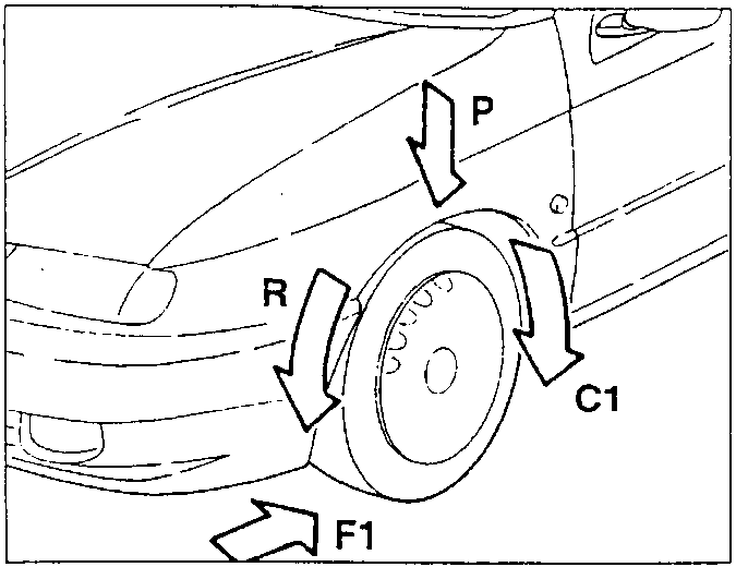
- C1 Braking torque
- F1 Braking force
- P Weight bearing on the tyre
- R Tyre rolling radius
During braking, braking friction increases decidedly, for low values of the slipping coefficient, then lowering, gradually as the wheel slows down with respect to the speed of the car. Maximum braking efficiency is therefore obtained with slipping coefficient between 5% and 15% with a maximum of 20% depending on the tyre and road surface.
The purpose of the wheel anti-lock system (A.B.S.) is that of modulating the braking pressure so that the slipping coefficient is always kept between optimum values: this will make it possible to brake with the maximum braking friction and stop the vehicle in the smallest space possible allowed by the condition of the road surface and the wear of the tyres.
ELECTROHYDRAULIC CONTROL UNIT
The control unit in the engine compartment is connected through unions (1) to the brake pump and through unions (2) to the braking system pipes.
The unit cannot be overhauled with the exception of relays (6) and (7), and muste be changed entirely if a fault is found. To replace the above-mentioned relays and the multiple socket (8), it is necessary to remove the cover (9) after slackening the fastening screw.
From the sensors in correspondence with the phonic wheels, the control unit receives information about the turning speed of the wheels, and processes it electronically. It then generates command signals which make it possible to hydraulically change the pressure of the brake fluid in the caliper cylinders.
Depending on the behaviour of the wheels, the electrohydraulic unit changes the pressure of the brake fluid at the calipers in three separate steps, as described in the previous paragraph.
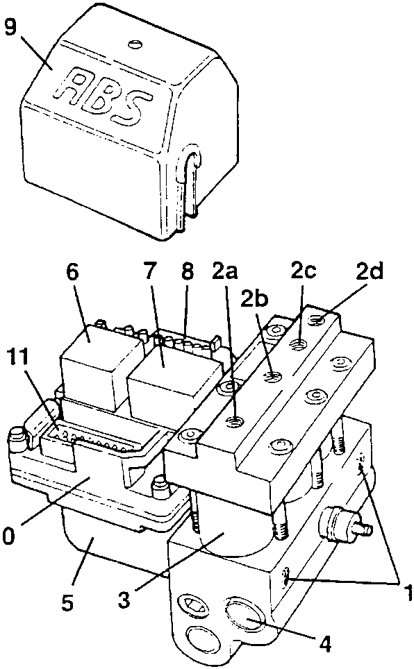
- Unions for connecting hydraulic unit - brake pump
- Unions for connecting hydraulic unit - pipes:
- a) left front caliper (VL)
- b) right rear caliper (HR)
- c) left rear caliper (HL)
- d) right front caliper (VR)
- Solenoid valves
- Sequential hydraulic valve
- Electric recovery pump
- Electric pump control relay
- Solenoid valve safety and supply relay
- Multiple connector
- Cover
- Electronic control unit
- 15-pole connector for hydraulic control unit
Parts & tools for this job For 1994 Alfa Romeo 145/146
- PARTBrake padsSearch: Alfa Romeo 145/146 1994 brake pads
- TOOLBrake bleeder kitSearch: one man brake bleeder kit
- FLUIDBrake fluidSearch: brake fluid
Links open Amazon search results in a new tab. As an Amazon Associate I earn from qualifying purchases.