
Electrohydraulic control unit
- Make
- Alfa Romeo
- Model
- 145/146 Factory Service Manual
- Year
- 1994–1999
- Section
- Anti-lock braking system (A.B.S.) › Electrohydraulic control unit
The electronic control unit is informed that the driver is braking by the signal from the switch on the brake pedal. Besides controlling braking, this information is also helpful under certain particular conditions, such as for example if a sharp acceleration that makes the wheels skid is followed by heavy braking, or in the case of irregular road surfaces (humps, steps) that can involve changes in speed of the wheel due to causes not linked with the braking in progress. In these conditions the microprocessors process a strategy connected with the changes of speed of the wheels of these particular moments, bringing braking back to the correct parameters. Since these are particular conditions of braking control, the lack of connection of the switch on the brake pedal to the control unit does not compromise the efficiency of the system. For this reason it is not signalled by the warning light, nor is the A.B.S. system disabled.
Further details about the operating principle of the ABS are given below.
Electrohydraulic control unit
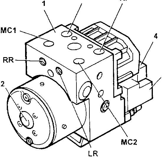
- Electrohydraulic control unit
- Electric recovery pump
- Electronic control unit
- Control unit connector
The electrohydraulic control unit is connected to the brake pump and to the brake caliper cylinders through the brake system lines and together with the electronic control unit it forms the electrohydraulic control unit.
Its task is to change the pressure of the brake fluid in the brake caliper cylinders according to the command signals leading from the electronic control unit. It comprises eight two-way solenoid valves (two for each hydraulic circuit) and an electric recovery pump (2) with double circuit.
The eight solenoid valves and the electric recovery pump are driven by the electronic control unit depending on the signals of the four rpm sensors. The pump makes it possible to recover the brake fluid during the pressure reduction phase making it available again upstream of the solenoid valves for the next pressure increase phase.
The unit is connected to the braking system through unions identified by the codes stamped on them as illustrated.
Pipe outlets
- MC1 Supply union from brake pump - circuit 1
- MC2 Supply union from brake pump - circuit 2
- LF Delivery union to left front brake caliper
- LR Delivery union to left rear brake caliper
- RF Delivery union to right front brake caliper
- RR Delivery union to right rear brake caliper
Inductive sensors
These are quite the same as those used for the previous versions.
Parts & tools for this job For 1994 Alfa Romeo 145/146
- PARTBrake padsSearch: Alfa Romeo 145/146 1994 brake pads
- TOOLBrake bleeder kitSearch: one man brake bleeder kit
- FLUIDBrake fluidSearch: brake fluid
Links open Amazon search results in a new tab. As an Amazon Associate I earn from qualifying purchases.