
Pressure reduction phase
- Make
- Alfa Romeo
- Model
- 145/146 Factory Service Manual
- Year
- 1994–1999
- Section
- Anti-lock braking system (A.B.S.) › Pressure reduction phase
Pressure reduction phase
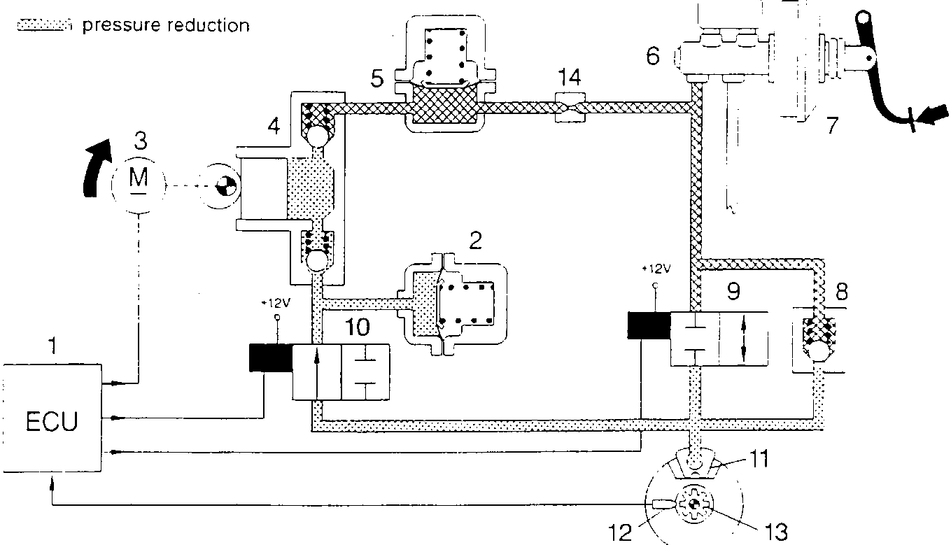
- Electronic control unit
- Low pressure accumulator (reservoir)
- Recovery pump drive motor
- Recovery pump
- High pressure accumulator (damping chamber)
- Brake control pump
- Servobrake
- Fast pressure reduction valve
- Charge solenoid valve
- Discharge solenoid valve
- Brake caliper
- Rpm sensor
- Phonic wheel
- Restrictor
The electronic control unit (1) detects the tendency of the wheel to lock and activates the electrohydraulic unit to keep deceleration of the wheel within the thresholds allowed.
The electronic control unit (1) connects to earth the charge (9) and discharge (10) solenoid valves.
The charge solenoid valve (9) remains closed keeping the connection between the brake pump (6) and brake caliper (11) shut; The discharge solenoid valve (10) opens putting the brake caliper (11) into hydraulic connection with the low pressure accumulator (2) and the recovery pump (4), in order to withdraw part of the fluid at the brake caliper (11) and reduce the pressure on the caliper itself.
Simultaneously, the electronic control unit (1) supplies the drive motor (3) of the recovery pump (4) which makes it possible to re-admit the fluid taken from the brake caliper (11) to the main circuit. The accumulator (2) or low pressure reservoir in the circuit has the task of storing part of the brake fluid taken from the calipers. Through the circuit of the recovery pump (4), the fluid is withdrawn and sent, via the damping chamber (5) and the restrictor (14), into the main circuit of the brake pump (6). In this phase a series of pressure waves (or hydraulic thrusts) are generated which are dampened by the presence of the damping chamber (5) and the restrictor (14).
During braking, light pushes on the brake pedal are to be considered normal when the ABS system is operational. During this phase, due to the effect of the lowering of the braking force, the wheel tends to resume the reference speed calculated by the electronic control unit (1).
The type of braking is intermittent or by steps with a succession of the phases depending on the wheel rolling conditions and according to a repetitive cycle that is not perceived by the driver, in the form of jerks, owing to the quickness and frequency with which it occurs and because it is evened out by the inertia of the wheel which is prevented from reaching extreme skidding conditions because of the rapidity of the device.
Parts & tools for this job For 1994 Alfa Romeo 145/146
- PARTBrake padsSearch: Alfa Romeo 145/146 1994 brake pads
- TOOLBrake bleeder kitSearch: one man brake bleeder kit
- FLUIDBrake fluidSearch: brake fluid
Links open Amazon search results in a new tab. As an Amazon Associate I earn from qualifying purchases.