
Hydraulic system layout
- Make
- Alfa Romeo
- Model
- 145/146 Factory Service Manual
- Year
- 1994–1999
- Section
- Anti-lock braking system (A.B.S.) › Hydraulic system layout
BrakesHydraulic system layout
Hydraulic system layout
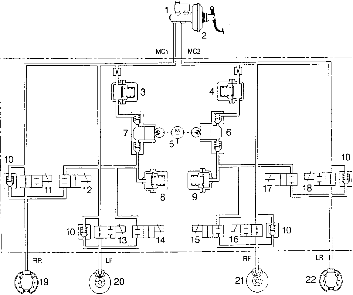
Braking system with double crossed circuit
- Brake control pump
- Servobrake
- High pressure accumulator (damping chamber)
- High pressure accumulator (damping chamber)
- Recovery pump drive motor
- Recovery pump
- Recovery pump
- Low pressure accumulator (reservoir)
- Low pressure accumulator (reservoir)
- Fast pressure reduction valve
- Right rear charge solenoid valve
- Right rear discharge solenoid valve
- Left front charge solenoid valve
- Left front discharge solenoid valve
- Right front charge solenoid valve
- Right front discharge solenoid valve
- Left rear charge solenoid valve
- Left rear discharge solenoid valve
- Right rear drum brake
- Left front disk brake
- Right front disk brake
- Left rear drum brake
MC1. Supply union for brake pump 1st stage
MC2. Supply union for brake pump 2nd stage
RR. Delivery union to right rear cylinder
FL. Delivery union to left front caliper
FR. Delivery union to right front caliper
RL. Delivery union to left rear cylinder
Parts & tools for this job For 1994 Alfa Romeo 145/146
- PARTBrake padsSearch: Alfa Romeo 145/146 1994 brake pads
- TOOLBrake bleeder kitSearch: one man brake bleeder kit
- FLUIDBrake fluidSearch: brake fluid
Links open Amazon search results in a new tab. As an Amazon Associate I earn from qualifying purchases.