
Structure of electrical/electronic system
- Make
- Fiat
- Model
- 500 Factory Service Manual
- Year
- 2007–2024
- Section
- Instrument/gauge electrical circuits › Structure of electrical/electronic system
Structure of electrical/electronic system
Structure of electrical/electronic system
The electrical equipment on this vehicle uses the "NANO F.L.ORE.N.C.E." structure developed specifically to incorporate the most up to date electronic functions in an optimum manner.
This structure makes up the car''s nervous system, directly controlling all the bodywork functions (access control, visibility, on board information, comfort, etc.) and communicates with the various chassis and power unit subsystems improving system fault diagnosis, reliability, weight and cost.
A further advantage compared with traditional systems is the simplified installation through the reduction in the number of control units (for the number of functions offered to customers) and the number of power and signal connections through the extensive use of serial communication networks (3 CAN twin wire communication networks, 1 single wire LIN subnetwork, 1 A-BUS single wire subnetwork).
Power distribution takes place by means of four junction units and relay/fuse boxes, connected to the control elements (static actuators and relays). These control units also act as an interconnection for the wiring and as an electrical distributor to ensure the maximum level of electrical protection and the minimum degree of wiring complexity.
It is a simplified version of the previous "MINI FLORENCE" system: the structure has been simplified to manage a greater number of functions with the Body Computer.
The main electronic components managed by the NANO F.L.ORE.N.C.E. structure are listed below:
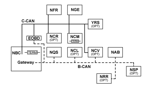
NBC. Body Computer Node
NFR. Brake node
NGE. Electric steering node
YRS. Slewing sensor - Hill holder
NCR. Robotized gearbox node
NCM. Engine management node
NQS. Instrument panel node
NCL. Climate control node
NCV. Convergence node
NAB. Air bag node
NSP. Parking sensor node
NRR. Radio receiver node
EOBD. Diagnostic connector
The structure of the communication lines includes:
- A 50 Kbit/s B-CAN type network. Specifications: presence of two network cables, B-CANb and B-CANa, resistant to network malfunctions; 29 bit standard
- A 500 Kbit/s C-CAN type network. Specifications: presence of two network cables, C-CANH and C-CANL, not resistant to network malfunctions; 29 bit standard
No faults present:
- The K communication lines for fault diagnosis of the C-CAN components;
- The discreet line for controlling the Engine Management Node MIL warning light; a 500 Kbit/s C-CAN type network. Specifications: presence of two network cables, C-CANH and C-CANL, not resistant to network malfunctions; 29 bit standard
- The W communication line for CODE function recovery
Components
The following components are connecte do the C-CAN:
- NBC: Body Computer Node;
- NFR: Brake Node;
- NCR: Robotised Gearbox Node (OPT);
- NGE: Electric Steering Node (OPT);
- NCM: Engine Management Node;
- YRS: Slewing Sensor Node (OPT).
Type of nodes
The following types of Nodes can be identified for the B-CAN.
- B-CAN Master +30: NBC Body Computer Node;
- B-CAN Slave +30: NQS Instrument Panel Node, NRR Radio Receiver Node (OPT).
- B-CAN Slave +30 (not time critical): NCV Convergence Node (OPT);
- B-CAN Slave +15: NCL Climate Control Node (OPT), NSP Parking Sensor Node (OPT), NAB Air Bag Node.
Whilst for the C-CAN
- C-CAN terminal node (primary): NBC Body Computer Node, NCM Engine Management Node;
- C-CAN terminal node (secondary): NCV Convergence Node (OPT)
- C-CAN nodes that allow network transit: NFR Brake Node, NGE Electric Steering Node (OPT), NCR Robotized Gearbox Node (OPT), YRS Slewing Sensor Node (OPT).
The node that allows the Gateway function, in other words the passage of information between one network and the other and viceversa, it the Body Computer Node.
PROXY alignment
The following electronic units are subject to PROXY alignment if replaced in an after-sales service situation:
- NBC
- NQS
- NCV
- NAB.
Fault diagnosis and diagnostic connector
The diagnostic connector (EOBD connector) is outside the Body Computer Node and joins the two CANs therefore the fault diagnosis at the nodes is carried out exclusively using diagnostic messages sent via the communication networks.
It is absolutely vital to have the A16HS diagnostic connector in order to be able to converse with the various electronic units.
The following electronic units can be diagnosed using the EXAMINER:
- NBC;
- NFR;
- NCM;
- NGE (OPT);
- NQS;
- NCV (OPT);
- NCR (OPT);
- NSP (OPT);
- NAB.
Body Computer Node
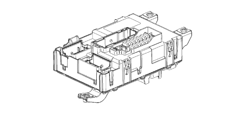
The Body Computer Node is illustrated below.
The rear part of the Body Computer Node is illustrated below.
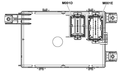
| Connector M001D PIN OUT | |
|---|---|
| Pin | Function |
| 1 | Immobilizer Aerial (Earth) |
| 2 | Immobilizer Aerial (Signal) |
| 3 | Negative signal from heated rear windscreen switch |
| 4 | F serial line for ABS / Doors LINE |
| 5 | A-bus line for rain sensor |
| 6 | Right direction indicators negative control from steering column switch unit |
| 7 | Hazard warning lights switch negative control |
| 8 | "UP" negative control on driver''s window |
| 9 | VSO signal generation |
| 10 | Hazard warning lights LED control |
| 11 | Door status LED control |
| 12 | Heated rear windscreen LED positive control |
| 13 | "DOWN" negative control on driver''s window |
| 14 | "UP" negative control on passenger window |
| 15 | "DOWN" negative control on passenger window |
| 16 | B CAN-A Air Bag Node |
| 17 | B CAN-A NRR, NCV |
| 18 | B CAN-A NQS |
| 19 | B-CAN A Diagnostic socket |
| 20 | B CAN-B NQS |
| 21 | B CAN-B Air Bag Node |
| 22 | B CAN-B NRR, NCV |
| 23 | B-CAN B Diagnostic socket |
| 24 | C CAN-H NCV (Stub) |
| 25 | C CAN-H EOBD (Stub) |
| 26 | C CAN-L NCV (Stub) |
| 27 | C CAN-L EOBD (Stub) |
| 28 | City / Sport button negative control |
| 29 | Boot internal switch signal / Tailgate (locking/unlocking) locking control switch signal |
| 30 | Front fog light switch signal |
| 31 | A/C request signal |
| 32 | Not connected |
| 33 | Reference earth to cruise lever signal |
| 34 | Reference earth to steering column switch unit signal |
| 35 | Clock spring reference earth signal |
| 36 | Main beam/flasher negative control from steering column switch unit |
| 37 | Reference earth for CSS |
| 38 | Dipped beam negative control from steering column switch unit |
| 39 | Opening/closing switch signal |
| 40 | Boot internal switch signal |
| 41 | Rear screen washer negative control from steering column switch unit |
| 42 | Horn control steering wheel 1 control |
| 43 | Opening/closing rear switch signal |
| 44 | Left direction indicators negative control from steering column switch unit |
| 45 | FN/RN control from CSS |
| 46 | Not connected |
| 47 | Not connected |
| 48 | Not connected |
| 49 | CSS reference earth |
| 50 | Radio controls on the steering wheel 2 (VOL-; VOL+; Mute; Voice) |
| 51 | Signal controlling side lights from steering column switch unit |
| 52 | Radio controls on the steering wheel 3 (SCAN -; SCAN +; Source; TEL) |
| 53 | Not connected |
| 54 | Front windscreen wiper first speed negative control from steering column switch unit |
| 55 | Front windscreen washer negative control from steering column switch unit |
| 56 | Front windscreen wiper second speed negative control from steering column switch unit |
| 57 | Front windscreen wiper intermittent speed negative control from steering column switch unit |
| 58 | Not connected |
| 59 | Rearscreen wiper negative control from steering column switch unit |
| 60 | Fixed lighting controlled by the side lights for radio preparation |
| Connector M001E PIN OUT | |
|---|---|
| Pin | Function |
| 1 | INT/A from ignition switch |
| 2 | Preparation (+30) |
| 3 | Supply for Air Bag |
| 4 | Supply for radio preparation |
| 5 | Supply for Convergence |
| 6 | INT/A for CCO |
| 7 | Supply for NQS |
| 8 | Dipped headlamps positive signal for headlamp alignment control at NQS |
| 9 | Power earth 1 for NBC |
| 10 | Power earth 2 for NBC |
| 11 | INT from ignition switch |
| 12 | +30 radio power supply |
| 13 | INT Electric Window Controls Lighting |
| 14 | +30 NQS power supply |
| 15 | INT lighting CSS |
| 16 | INT additional panel for climate control / ASR button lighting |
| 17 | INT SWC Controls lighting |
| 18 | Glove compartment light |
| 19 | +30 Supply for Convergence |
| 20 | +30 for Diagnostic Socket |
The front part of the Body Computer Node is illustrated below.
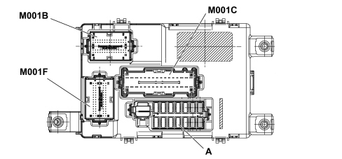
A. Fuses
| Connector M001B PIN OUT | |
|---|---|
| Pin | Function |
| 1 | Horn relay control |
| 2 | Relay KL15 control (T6) |
| 3 | WLM window opening mechanism |
| 4 | Fog lights relay negative control |
| 5 | Door open negative signal to NCR control unit |
| 6 | Heated rear windscreen relay negative control |
| 7 | Front puddle lights |
| 8 | Right front flasher |
| 9 | Right side flasher |
| 10 | Left front flasher |
| 11 | Left side flasher |
| 12 | Left Brake Light |
| 13 | Right DRL light |
| 14 | Comfort enable supply |
| 15 | Right front side light (left and right) |
| 16 | Relay KL15a control (T5) |
| 17 | Door status LED operation |
| 18 | Hazard warning lights signal |
| 19 | VSO output generation |
| 20 | Hazard warning lights control |
| 21 | Heated rear windscreen LED operation |
| 22 | Main beam headlamps relay negative control |
| 23 | Preparation |
| 24 | Passenger door limit switch |
| 25 | Speedometer sensor / TPMS earth (GND) |
| 26 | Front brake pad wear signal |
| 27 | Brake lights control from brake pedal (NA), Third brake light |
| 28 | Left DRL light |
| 29 | Left front side light (front/rear or left/right) |
| 30 | Right front side light (front/rear) |
| 31 | Relay KL15 control (T30) |
| 32 | "UP" switch signal on driver''s window |
| 33 | Negative signal from brake fluid level sensor |
| 34 | Brake lights switch signal (NC) |
| 35 | TPMS 1 signal |
| 36 | TPMS 2 signal |
| 37 | Outside temperature sensor signal |
| 38 | "UP" switch signal on passenger window |
| 39 | Front windscreen wiper stop contact signal |
| 40 | "DOWN" switch signal on driver''s window |
| 41 | Heated rear windscreen switch signal |
| 42 | B CAN-A Diagnostic socket (preparation) |
| 43 | B CAN-B Diagnostic socket (preparation) |
| 44 | C CAN-H NBC (network start) |
| 45 | C CAN-L NBC (network start) |
| 46 | Dipped headlamps relay control |
| 47 | "DOWN" switch signal on passenger window |
| 48 | Boot open switch signal (NA) |
| 49 | A/C request signal |
| 50 | Speedometer sensor signal |
| 51 | Driver''s door limit switch |
| 52 | Outside temperature sensor (GND) |
| 53 | Passenger door open switch signal |
| 54 | Dirver''s door open switch signal |
| 55 | Serial line for ABS doors LIN |
| 56 | A-BUS line for rain sensor |
| 57 | B CAN-A Climate Control System Control Unit |
| 58 | B CAN-B Climate Control System Control Unit |
| 59 | High Speed CAN-H |
| 60 | High Speed CAN-L |
| Connector M001E PIN OUT | |
|---|---|
| Pin | Function |
| 1 | Left front electric windows "DOWN" control |
| 2 | Two-way pump (rearscreen washer) |
| 3 | Front windscreen wiper motor (low speed operation) |
| 4 | Preparation (KL15) |
| 5 | Preparation (KL15) |
| 6 | INT for ECO / SPORT MTA switch |
| 7 | INT to NA brake pedal |
| 8 | INT for Electric mirrors control |
| 9 | INT for CTA |
| 10 | Supply for left dipped headlamp bulb |
| 11 | Left headlamp alignment corrector actuator |
| 12 | +30 Preparation |
| 13 | Supply for rearscreen wiper |
| 14 | Front windscreen wiper motor (high speed operation) |
| 15 | Two-way pump (windscreen washer) |
| 16 | Central locking (closing/opening) |
| 17 | Right front electric windows "DOWN" control |
| 18 | Right front electric windows "UP" control |
| 19 | Left front electric windows "UP" control |
| 20 | Puddle light (SBMT) |
| 21 | INT/A for engine compartment junction unit |
| 22 | INT for Electric mirrors control lighting |
| 23 | Preparation (KI15) |
| 24 | INT for NCL climate control unit |
| 25 | INT to NC brake pedal |
| 26 | Right headlamp alignment corrector actuator |
| 27 | Supply for right dipped headlamp bulb |
| 28 | +30 Preparation |
| 29 | +30 Supply for NCL |
| 30 | Tailgate unlocking control |
| 31 | Joint door locking/unlocking |
| 32 | Central door locking (DEAD-LOCK) |
| Connector M001F PIN OUT | |
|---|---|
| Pin | Function |
| 1 | Left rear flasher |
| 2 | Left side flasher |
| 3 | Right rear flasher |
| 4 | Fuel level sensor signal |
| 5 | Right rear side light (Front/rear or left/right) |
| 6 | Left rear side light (left/right) |
| 7 | Negative signal from rear wiper cam |
| 8 | Right brake light |
| 9 | Front courtesy light timed control |
| 10 | Left rear fog lamp control |
| 11 | Boot light operation |
| 12 | Rear courtesy light operation |
| 13 | Front courtesy light power supply (SBMT) |
| 14 | Parking sensor power supply |
| 15 | Number plate light |
| 16 | Third brake light |
| 17 | Fuel level negative signal (GND) |
| 18 | Right side flasher |
| 19 | Handbrake applied switch negative signal |
| 20 | Left rear side light (front/rear) |
| 21 | Not connected |
| 22 | Front courtesy light switch signal |
| 23 | INT for Convergence control lighting |
| 24 | INT for Electrochromic mirror |
| 25 | Rear fog lamp operation |
| 26 | Boot Light Power Supply (SBMT) |
| 27 | Preparation (SBMT) |
| 28 | Passenger sun visor light power supply |
| 29 | INT/A for SCM |
| 30 | Fixed lighting controlled by the side lights for cigar lighter |
| 31 | FR aerial (GND) coaxial cable |
| 32 | Heated rear windscreen relay feed |
| 33 | F serial line for ABS / doors LIN |
| 34 | B CAN-A Parking sensor node |
| 35 | Not connected |
| 36 | Not connected |
| 37 | LS CAN-A |
| 38 | Tailgate opening negative control from Soft Touch handle |
| 39 | Tailgate open negative signal from switch |
| 40 | Left brake light |
| 41 | Not connected |
| 42 | Not connected |
| 43 | Not connected |
| 44 | Right fog light control/reversing light control |
| 45 | Right fog light control/reversing light control |
| 46 | RF aerial signal (coaxial cable) |
| 47 | WLM Comfort closing |
| 48 | A-BUS line for rain sensor |
| 49 | B CAN-B Parking sensor node |
| 50 | Not connected |
| 51 | Not connected |
| 52 | LS CAN-B |
| 53 | After market anti-theft signal |
| 54 | Boot internal switch signal / Tailgate (locking/unlocking) locking control switch signal |
| 55 | Preparation |
| 56 | Not connected |
| 57 | Not connected |
| 58 | Not connected |
| 59 | Not connected |
| 60 | Left brake light |
The fuses in the Body Computer are illustrated in the diagram below.
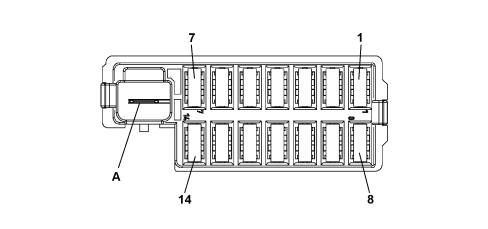
A. +30 NBC engine compartment junction unit
| Index | Identification | Type | Function | Capacity |
|---|---|---|---|---|
| 1 | F12 | A0 ( mini) | Right dipped headlamp power supply | 7.5 A |
| 2 | F13 | A0 ( mini) | Front, rear, boot and puddle courtesy lights. | 7.5 A |
| 3 | F53 | A0 ( mini) | NQS | 5 A |
| 4 | F38 | A0 ( mini) | Door central locking | 20 A |
| 5 | F36 | A0 ( mini) | Diagnostic socket NRR/Cell/NCL/EOBD | 10A |
| 6 | F43 | A0 ( mini) | Windscreen/rearscreen washer pump | 15 A |
| 7 | F48 | A0 ( mini) | Passenger side electric window | 20 A |
| 8 | F13 | A0 ( mini) | Left dipped headlamp and CAF power supply | 7.5 A |
| 9 | F50 | A0 ( mini) | NAB | 7.5 A |
| 10 | F51 | A0 ( mini) | switch for NRR/NCV/NCL/Brake lights switch (NC)/clutch switch | 7.5 A |
| 11 | F37 | A0 ( mini) | Brake lights switch (NA), NQS | 5 A |
| 12 | F49 | A0 ( mini) | Parking sensor, backlighting switches, electric mirrors | 5 A |
| 13 | F31 | A0 ( mini) | INT/A for engine compartment junction unit | 5 A |
| 14 | F47 | A0 ( mini) | Driver''s side electric window | 20 A |
Functions managed by NBC
Fuel cut off function control
There is no inertia switch on this vehicle; the fuel cut off function is managed in accordance with the logic described below:
1) the Air Bag control unit detects the impact and transmits the activation of the FPS (Fire Prevention System) via the CAN
2) after having received the FPS activation signal, the Body Computer Node:
- activates the hazard signal
- switches the courtesy light on
- unlocks the doors
- transmits that the impact has taken place via the CAN (B and C)
3) the instrument panel signals that the fuel cut off function has intervened
4) the engine management control unit interrupts the supply of fuel.
Rearming
The following procedure should be carried out using the steering column switch unit lever to restore the correct of the vehicle:
- KEY OFF (starting condition)
- KEY ON
- Activation of right indicator
- Deactivation of right indicator
- Activation of left indicator
- Deactivation of left indicator
- Activation of right indicator
- Deactivation of right indicator
- Activation of left indicator
- Deactivation of left indicator
- KEY OFF
Key recognition
When the ignition key is turned ON, the NBC converses with the NCM to recognize the key CODE, this dialogue takes place via the C-CAN and there is no W recovery line.
If there is a fault the NBC activates the MIL warning light in the Instrument Panel Node via a message on the B-CAN.
Fuel level
The NBC receives the signal from the level sensor integrated in the fuel pump, the vehicle speed and the engine rpm and then processes the information concerning the fuel level and sends messages about the: fuel level, reverse warning light engagement, error status at the B-CAN to the NQS.
It also transmits information via the C-CAN concerning the fuel level for the NCM.
Comfort function
When the ignition is turned OFF the NBC activates the comfort function for around 3 minutes allowing some of the functions to be maintained, such as, for example the operation of the electric windows.
The comfort function is deactivated when the doors are opened or if the key is turned off with the doors open.
Alternator signal management
The alternator is connected to the NCM which sends the status message via the C-CAN, the NBC processes this information to make the alternator charge status and a possible fault message available to the electronic units involved via both networks.
Acquisition of battery voltage
The NBC is connected directly to the battery and it evaluates the charge status and makes this information available at the B-CAN.
Minimum engine oil pressure
The minimum engine oil pressure sensor is connected directly to the NCM which measures the status and makes the information available on the C-CAN. The NBC makes it available on the B-CAN, through the GATEWAY function so that the NQS can acquire it for the management of the minimum oil pressure warning light.
Fuel consumption
The NCM transmits the fuel consumption information on the C-CAN, the NBC transmits this message, via the GATEWAY function, on the B-CAN for the TRIP COMPUTER function.
Eobd/mil warning light management
The NCM transmits the MIL/EOBD warning light status on the C-CAN, the NBC transmits this message on the B-CAN via the GATEWAY function.
The NQS reads the warning light status and manages the operation.
Heater plugs warning light management (diesel only).
The NCM manages the operation of the heater plugs control unit and transmits the activation status and any errors on the C-CAN.
The NBC transmits messages made available from the NCM on the B-CAN via the GATEWAY function.
The NQS acquires the messages and manages the heater plugs warning light.
Management of rear fog lamps
The NBC acquries the on command from the dedicated switch and, if the dipped headlamps are activated, it activates the rear fog lamps directly.
The on status of the rear fog lamps is transmitted on the B-CAN, the NQS acquires the message and activates the warning light/on message or the fault.
Management of rear fog lamps and fog lights
The NBC acquires the on command from the dedicated switch (there is only one switch) and, if the dipped headlamps are activated, it activates either the fog lights only or the fog lights and the rear fog lamps depending on the action taken by the driver.
The on status of the rear fog lamps is transmitted on the B-CAN, the NQS acquires the message and activates the warning light/on message or the fault.
The fog lights are switched off during starting.
Key status
The NBC acquires the key status (Off, INT/INT/A) from the ignition switch and transmits the key position status on the C-CAN and B-CAN.
Management of the direction indicators
The direction indicators are controlled directly, without the help of outside relays, by the NBC on the basis of the following request information:
- Left and right direction indicators control from steering column switch unit lever;
- Activation request from door unlocking function.
- Hazard warning lights switch.
- Request from (after market) anti-theft system
- Activation request from FPS function.
- Activation request from brake lights management function (see activation of hazard warning lights when braking paragraph)
When there is an activation the NBC transmits the message on the B-CAN to allow the NQ to activate the warning light/warning message.
This status messag is transmitted on the C-CAN
Direction change function
In the case of a change in direction, moving the direction indicators lever, the NBC controls the direction indicators directly from the left or right side selected.
Lane change function
In the case of a lane change, for example when overtaking on the motorway, as the result of operating the direction indicators lever for 500ms or less, the NBC controls the direction indictors on the side selected with three flashes.
Deactivation of lane change function
The function can be deactivated if whilst operating the lever the command is reversed by moving the lever in the opposite direction. It is possible to activate the lane change function in this way (activation of three flashes on the opposite side) or to activate the direction change function.
Hazard warning lights
Hazard warning lights with ignition off or on
The hazard warning lights are activated directly by the NBC when the dedicated button in the middle of the dashboard is activated.
Turning the key from on to off and viceversa has no effect on the activation of the lights.
Hazard warning lights control, activated together with the direction change function activation control.
If the direction change control is activated whilst the hazard warning lights control is activated, or if the hazard warning lights function is activated whilst the direction change control is activated, the hazard warning lights function takes precedence.
Ess (emergency stop signalling) braking hazard warning lights activation function
In the case of braking with deceleration above 7(+/-0.5)m/s², vehicle speed above 50 km/h, hazard warning lights control deactivated and speed signal not faulty, the NBC estimates the deceleration level and activates the hazard wanring lights until the NBC estimates that the deceleration level has gone below 2.5 (+/-0.5)m/ s².
The lights are activated at a higher frequency than the hazard warning lights function
Hazard warning lights activation function in the case of fps function activation (fire prevention system)
If the fire prevention system is activated, when the key is turned on the hazard warning lights are immediately activated; during the system rearming stage, if the steering column switch unit lever is moved, the direction indicators on the side selected will be activated to confirm the receipt of the command.
For more details see
For petrol engines:
See descriptions 1056 PETROL INJECTION SYSTEM
For diesel engines:
See descriptions 1060 DIESEL INJECTION SYSTEM
Activation of hazard warning lights for vehicle access function
The hazard warning lights are activated by the NBC in accordance with the central locking function as follows:
- When the doors are locked in the locked status, the hazard warning lights are activated for 1 second
- When the doors are locked in the open status, the lights flash for three seconds.
- When the doors are unlocked they flash for two seconds.
- When the boot is opened they flash for one second.
Activation of hazard warning lights for anti-theft function
When the command is received from the anti-theft system, the NBC activates the hazard warning lights which are then deactivated when the subsequent deactivation command is sent.
Recovery and fault diagnosis
The front and rear lights are controlled by the NBC and, if there is a problem, it transmits the message on the B-CAN and, if one of the lamps is not working, the NBC duplicates the flashing frequency value.
Brake switch position function
The NBC receives the "normally open" and "normally closed" switch status for the brake position sensor through a direct connection and transmits the "normally closed" switch status via the C-CAN.
The NCM receives the "normally open" switch status through a direct connection and the "normally closed" switch status via the C-CAN.
The NFR receives the "normally open" switch status through a direct connection and the "normally closed" switch status via the C-CAN.
This function makes it possible to acquire the brake pedal position status and plausibility control by the electronic units involved.
Brake lights activation
The NBC acquires the brake pedal "pressed/released" status from the brake pedal "normally open" switch and activates the left and right brake lights directly, the third brake light is activated directly by the "normally open" switch.
If there is a problem, the NBC transmits the error message via the B-CAN which is received by the NQS which, in turn, activates the warning light/message.
Interior lights without dimming
The interior lights comprise various LEDs which light up the various buttons which are activated when:
- A) There is a transition from the key from off to on (+15). The following interior lights are involved: left and right electric window control lighting, ECO/SPORT button lighting, centre control panel lighting, auxiliary control panel lighting, controls on the steering wheel lighting, NCL and electric mirrors control and lighting
- B) From the NBC with the ignition on via the interior lights without dimming control. The following lights are involved: cigar lighter light, current socket light, ashtray light, heater controls light.
The NBC receives the status of the NQS instrument panel lights from the B-CAN and transmits the activation status of the interior lights without dimming on the B-CAN.
Interior lights
The following interior lights are present on the vehicle:
- Ceiling courtesy light
- Sun visor light
- Boot light
The NBC allows the activation, with the key ON, of these lights through the switches, via the "deliberate light activation" signal.
This signal can may also be present with the key OFF when the following conditions occur:
- Opening of one of the doors using the remote control
- Opening of one door
- Opening of the boot.
- Activation of sun visor switch.
- Activation of courtesy light switch
In this case the activation time for the "deliberate light activation" signal is 15 minutes.
Ceiling courtesy light
The ceiling courtesy light can be activated using the switch on the courtesy light with the following possible actions:
- Courtesy light on
- Deactivation/activation of BCM courtesy light control (NBC):
The NBC can control the courtesy light directly in the following circumstances:
- When one of the doors is opened (activation time about 3 minutes)
- When one of the doors is closed (activation time about 10 seconds)
- When the key is extracted with the comfort function activated (activation time about 10 seconds)
If the FPS function is activated (activation time: about 15 minutes) in this case only the rearming of the FPS function can reset the time counter.
the position of the key e.g. going from OFF to ON determines the activation or deactivation of the courtesy light
On versions without central locking, the NBC can activate the front courtesy light if:
- One of the doors is opened
- Intervention of the FPS
Brake wear check
The NBC acquires the brake wear signal through a direct connection to one of the left front brake pads.
As well as wear of the pad, a metal insert in the material and in contact with the disc is uncovered, establishing an earth connection for the lead to which it is connected.
The earth signal is then transmitted to the NBC. The NBC sends a message to the NQS via the B-CAN which turns on the warning light.
Engine compartment junction unit
The engine compartment junction unit is incorporated in the engine compartment cable loom and cannot be replaced on its own.
Fuses and relays
The following diagram shows the engine compartment junction unit
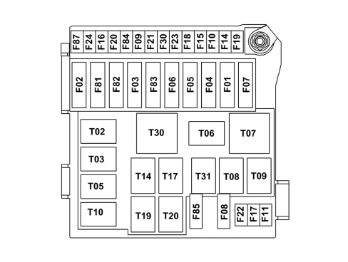
| Fuse | Ampere | Consumers protected |
|---|---|---|
| F01 | 60 | NBC |
| F02 | 20 | Subwoofer, Hi-fi audio amplifier |
| F03 | 20 | Ignition switch |
| F04 | 40 | NFR 1 (pump) |
| F05 | 70 | EPS (NGE) |
| F06 | 20/30 | Input T06 (engine cooling fan low speed) |
| F07 | 30/40 | Engine cooling fan high speed |
| F08 | 30 | Climate control fan |
| F09 | Spare (trailer) | |
| F10 | 15 | Horns |
| F11 | 10 | Engine management system (secondary loads) |
| F14 | 15 | Main beam headlamps |
| F15 | 20 | Electric roof motor (where fitted) |
| F16 | 7,5 | +15 NCM, NCR, dualogic robotized gearbox control, relay T20 coil |
| F17 | 10 | NCM |
| F18 | 7,5 | NCM, (1.2 8V) |
| F18 | 7,5 | NCM, relay T09 coil (1.4 16V, 1.3 Multijet) |
| F19 | 7,5 | Air conditioning compressor |
| F20 | 30 | Heated rear windscreen, electric mirrors defrosters (NCL) |
| F21 | 15 | fuel pump |
| F22 | 15 | Ignition coil, injectors (1.2 8V) |
| F22 | 20 | NCM (1.3 Multijet injectors) |
| F23 | 20 | NFR 2 (ECU, valves) |
| F24 | 7,5 | +15 NFR, EPS (NGE), YRS |
| F30 | 15 | Fog lights |
| F81 | 50 | Heater plugs control unit (1.3 Multijet) |
| F82 | spare | |
| F83 | 30 | Dualogic gearbox power assisted pump (where fitted) |
| F84 | 10 | NCR (control unit, solenoid valves) |
| F85 | 15 | Front current socket (with or without cigar lighter) |
| F87 | 7,5 | +15 for reversing lights, flow meter, water in diesel presence sensor, coils for relays T02, T05, T14 and T19 |
| Relay | Ampere | Consumers operated |
|---|---|---|
| T02 | 20 | Main beam headlamps |
| T03 | 20 | Horns |
| T05 | 20 | Air conditioning compressor |
| T06 | 30 | Engine single speed cooling fan Engine cooling fan low speed |
| T07 | 50 | Engine cooling fan high speed |
| T08 | 30 | Climate control fan |
| T09 | 30 | Engine management system (main relay) |
| T10 | 20 | Spare |
| T14 | 20 | Fog lights |
| T17 | 30 | Fuel pump |
| T19 | 30 | Heated rear windscreen |
| T20 | 30 | Starting inhibition with robotized gearbox |
| T30 | 50 | Dualogic gearbox power assisted pump (where fitted) |
| T31 | 30 | Front current socket (with or without cigar lighter) |
Central locking function
The NBC acquires the signals coming from the switches in the locks for the management of the central locking. This signals make it possible to identify the status of:
- Door closed
- Door open
- Door locked
- Request to unlock doors via key or interior handle
- Door unlocked
- Request to lock doors via key or interior handle
- Boot open
- Boot closed
- Request to open boot from switch on handle
It receives the following through the internal function:
- The locking/unlocking command for the doors and the boot via the remote control
- Intervention of the FPS
- Vehicle speed
- Recognition of the CODE transponder
- The request to lock/unlock the doors and release the boot
The activation status of the door lock at speeds above 20 km/h is also received by the NQS via the B-CAN.
Having received the various commands/messages, the NBC controls the door and boot lock motors, activates the hazard warning lights and transmits the door status on the B-CAN and the C-CAN.
The commands are direct.
For more details see:
Door locking functions detail
Recognition of door status
The NBC recognizes the door and boot open or closed status via the dedicated switches and this information is transmitted on the CANs.
My car personalization
the NBC receives the door locking function activation status at speeds above 20 km/h from the NQS via the B-CAN if the speed level is activated it activates the door/tailgate locking control.
The function is only activated if the doors are closed and if the speed level is exceeded for less than 200 ms.
If the speed of the vehicle goes below the speed level the doors are not unlocked.
If the doors are unlocked after having been locked, the function is reactivatedwhen the speed level is exceeded.
Recognition of locking/unlocking status by lock internal switch
There is a switch inside the door locks which is designed to recognize the lock locked/unlocked status; this switch is also designed to control the unlocking/locking via the metal insert for the key and the internal levers.
When a variation in the status of this switch is recognized, the NBC controls the unlocking or the locking of all the locks
Locking/unlocking using remote control
When signals from the remote control are received the locks are activated as set out in the table below.
| Type of command | Type of press on button | Action |
|---|---|---|
| Door unlocking button | Single press | Unlocking control Flashing of hazard warning lights |
| Double press | Unlocking control | |
| Door locking button | Single press | Unlocking control Flashing of hazard warning lights |
| Boot button | Single press | Boot release Flashing of hazard warning lights |
Control from (after market) anti-theft system
When signals from the anti-theft device are received the locks are activated as set out in the table below.
| Type of command | Type of press on button | Action |
|---|---|---|
| Unlocking command from anti-theft remote control | Single press | Unlocking the doors Hazard warning lights activation |
| Locking command from anti-theft remote control | Single press | Locking the doors Hazard warning lights activation |
| Boot release command from anti-theft remote control. | Single press | Boot release Hazard warning lights activation |
Signalling of lock locking and unlocking actions (using remote control only).
If the doors and the tailgate are locked and unlocked, the hazard warning lights are activated (see paragraph).
Locking of the doors with one door or the boot open
If one of the doors or all the doors are open, the locking command is rejected by all the doors.
If the boot is open, the locking of the doors takes place normally.
Management of the boot lock
The boot is managed like a third door, therefore when the doors are locked the boot is also locked and the doors are unlocked the boot is also unlocked.
When the boot lock is unlocked, the boot can be opened using the button in the exterior handle and conversely when the lock is locked the boot cannot be opened.
If the boot is opened mechanically the logic status does not change, when it is closed again the status of the other doors is automatically aligned.
The boot cannot be opened above 20 km/h to prevent it being opened accidentally by vibrations produced for example over unmade roads.
Unlocking of the locks by fps
When the FPS activated status is recognized, the NBC immediately unlocks all the locks,
Inhibition after various locking/unlocking commands
After 10 repeated commands in 25 seconds the NBC disables the unlocking and locking commands as follows:
- if the last command is for unlocking the doors, the NBC prevents a subsequent unlocking or locking for 30 seconds;
- if the last command is for locking the doors, the NBC inhibits the subsequent locking for 30 seconds and during this period the NBC only accepts a door unlocking command.
If the FPS is activated, the unlocking command is carried out.
Connection to +30
On connection to the +30 the NBC does not accept commands for at least 2 seconds, in addition the NBC does not recognize the status of the doors until a central command from the key, the remote control, the anti-theft remote contro or the FPS is activated.
Electric window operation with automatic function
The NBC receives signals coming from the switches in the central control panel to operate the electric window motors and it also checks the key status to manage the motors and the comfort function status if the key is OFF and the motors are controlled directly by the NBC.
Operating mode
The NBC can operate the motors in two ways:
- manual mode, activated when the action on the switch takes place in a time of between 50 and 300ms;
- automatic mode, activated when the action on the switch takes longer than 300ms.
The NBC interrupts the action on the motors when the command is reversed e.g. going from a closing command to an opening command or when the upper or lower limit is reached.
There is no anti-crush safety function.
For more details see:
See E3050 ELECTRIC FRONT WINDOWS
Ess (emergency stop signalling) braking hazard warning lights activation function
In the case of braking with deceleration above 7(+/-0.5)m/s², vehicle speed above 50 km/h, hazard warning lights control deactivated and speed signal not faulty, the NBC estimates the deceleration level and activates the hazard wanring lights until the NBC estimates that the deceleration level has gone below 2.5 (+/-0.5)m/ s².
the lights are activated at a higher frequency than the hazard warning lights function
For more details see:
Parts & tools for this job For 2007 Fiat 500
- TOOLDigital multimeterSearch: automotive digital multimeter
- PARTAssorted fuse kitSearch: car fuse assortment kit
- TOOLWire crimper and connector kitSearch: wire crimper connector kit
Links open Amazon search results in a new tab. As an Amazon Associate I earn from qualifying purchases.