
Bonnet wiring - r.r.
- Make
- Fiat
- Model
- 500 Factory Service Manual
- Year
- 2007–2024
- Section
- Instrument/gauge electrical circuits › Bonnet wiring - r.r.
BONNET WIRING - R.R.
Removing
See the Wiring Diagrams section for accurate identification of the electrical connections.
- Position the vehicle on a lift.
Before working on the air bag system, it is essential to perform the following preliminary operations.
(1) put the ignition key in the STOP position and extract it;
(2) disconnect the battery terminals and insulate;
(3) wait for at least 10 minutes before continuing.
FOLLOW ALL THE RECOMMENDED SAFETY INSTRUCTIONS
Op. 0010T84 COOLANT FOR AIR CONDITIONING SYSTEM - DEHYDRATE AND REPRESSURIZE
- Have a suitable container ready for collecting the coolant.
Op. 0010T20 ENGINE COOLANT - CHANGE
Op. 1048A23 COLD AIR INTAKE FOR AIR FILTER - R.R
Op. 1048A10 AIR FILTER ASSEMBLY - R.R.
- THE FOLLOWING OPERATIONS ARE SPECIFICALLY FOR 1.3 Multijet VERSIONS
Op. 1044B10 FUEL FILTER ASSEMBLY - R + R OR REPLACE
- THE FOLLOWING OPERATIONS ARE VALID FOR ALL VERSIONS.
Op. 5530B52 BATTERY SUPPORT/DRIP TRAY - R.R
- THE FOLLOWING OPERATIONS ARE SPECIFICALLY FOR 1.3 Multijet VERSIONS
Op. 1048B44 RIGID AIR SUPPLY PIPE BETWEEN HEAT EXCHANGER AND INTAKE MANIFOLD - R.R.
- THE FOLLOWING OPERATIONS ARE VALID FOR ALL VERSIONS.
Op. 5010A12 HEATER WATER SUPPLY PIPE - R.R.
Op. 5050B34 WINDSCREEN WIPER ARM/S COMPLETE WITH BLADE - R+R
Op. 7210E22 R.R. WINDSCREEN BASE TRIM
Op. 5050B42 WINDSCREEN WIPER MOTOR - R+R
Op. 4450B12 FRONT WHEELS (TWO) - R+R
Op. 4410D22 BRACKET FIXING FRONT SUSPENSION CROSSMEMBER TO BODYSHELL (ONE), LEFT OR RIGHT - R.R.
Op. 7055B66 ENGINE COMPARTMENT DUST COVER IN RIGHT FRONT WHEEL ARCH - R.R.
- Remove both front pillar trims
Op. 7040H30 FRONT PILLAR TRIM (ONE), LEFT OR RIGHT - R.R.
- Remove both the sun blinds.
Op. 7065C34 SUN BLIND (ONE), LEFT OR RIGHT - R.R.
Op. 7040E10 FRONT COURTESY LIGHT - R+R
- Remove both upper elements of the centre pillar covers.
Op. 7040H38 CENTRE PILLAR UPPER ELEMENT (ONE), LEFT OR RIGHT - R.R
Op. 7040H10 ROOF PANEL LINING - R.R.
- If the vehicle is provided with a knee protection Air Bag
Op. 5580C23 DRIVER'S KNEE BAG - R.R.
Op. 7040A30
Op. 7040A26 STEERING COLUMN TRIM - R+R
Op. 5580E08 AERIAL FOR ELECTRONIC KEY (CODE) - R.R
Op. 5580C18 AIR BAG MODULE - R+R
Op. 4110A10 STEERING WHEEL - R+R FOR REPLACEMENT OR CHECKS
Op. 5550A10 STALK UNIT ASSEMBLY - R+R
Op. 7040A23 INSTRUMENT PANEL FRAME IN DASHBOARD - R.R
Op. 5560B10 CONTROL PANEL - R+R
Op. 2125C24 GEAR LEVER KNOB - R + R
Op. 2125C02 GEAR CONTROL LEVER OUTER BOOT - R.R.
Op. 7040A28 TRIM ON GEARBOX CONTROL PANEL - R.R.
- Remove both centre console side trims:
Op. 7040A65 CONSOLE SIDE CLOSING (ONE) - R.R.
- Remove both electric window switches:
Op. 7005M10 ELECTRIC WINDOW CONTROL SWITCH (ONE) FOR ONE FRONT DOOR - R.R.
Op. 7040A56 SWITCH UNIT IN DASHBOARD - R.R.
Op. 7040A41 SPEAKER GRILLE (ONE) LH OR RH ON INSTRUMENT FACIA - R R
Op. 7040A49 CONNECTOR HOLDER TRIM FOR EOBD - R.R.
Op. 7040A44 LEFT DASHBOARD SIDE TRIM - R.R.
Op. 5570T80 CAR RADIO EQUIPMENT - R+R
Op. 5010C30 CENTRAL AIR VENT IN DASHBOARD - R.R.
Op. 5010C12 WINDSCREEN DEMISTER DIFFUSER - R+R
- Remove both diffusers:
Op. 5010C26 FRONT SIDE PANEL AIR DIFFUSER, L.H. OR R.H. - R R
- Remove both side doors.
Op. 7210E36 R.R. FRONT SIDE DOOR
Op. 7040A10 DASHBOARD TRIM - R+R
- Remove both front pillar trims:
Op. 7040H30 FRONT PILLAR TRIM (ONE), LEFT OR RIGHT - R.R.
Op. 4110D20 STEERING ELECTRICAL CONTROL DEVICE - R R
Op. 5010C55 RIGHT LOWER AIR DIFFUSER - R+R
Op. 7210A74 R R FACIA SUPPORT BEAM
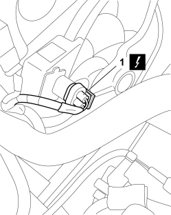
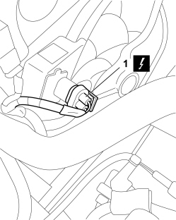
1. Disconnect the electrical connection for the engine cooling fan adjustment heating coil.
| Description | Connector | |
|---|---|---|
| 1 | ENGINE FAN ADJUSTMENT HEATING COIL - 1 | See O010 ENGINE FAN ADJUSTMENT RESISTANCE - 1 |
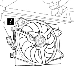
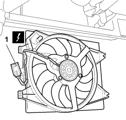
1. Disconnect the electrical connection for the engine cooling fan.
| Description | Connector | |
|---|---|---|
| 1 | ENGINE FAN MOTOR | See N011 FAN MOTOR |
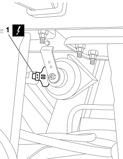
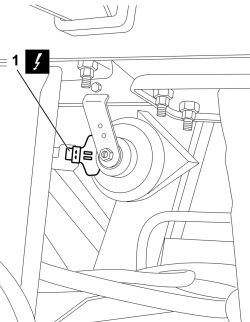
1. Disconnect the electrical connection for the horn.
| Description | Connector | |
|---|---|---|
| 1 | SINGLE-TONE HORN | See P005 SINGLE-TONE HORN |
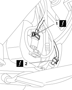
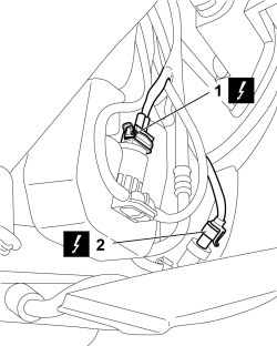
1. Disconnect the electrical connection for the windscreen washer pump.
| Description | Connector | |
|---|---|---|
| 1 | WINDSCREEN/REARSCREEN ELECTRIC WASHER PUMP MOTOR | See N022 WINDSCREEN WASHER/ REAR WINDOW WASHER PUMP MOTOR |
2. Disconnect the electrical connection for the linear pressure switch.
| Description | Connector | |
|---|---|---|
| 2 | LINEAR SENSOR FOR FANS | See K120 LINEAR SENSOR FOR FANS |
- THE FOLLOWING OPERATIONS ARE SPECIFICALLY FOR 1.3 Multijet VERSIONS
1. Disconnect the electrical connections for the heater plugs control unit.
| Description | Connector | |
|---|---|---|
| 1 | GLOW PLUG PREHEATING CONTROL UNIT | See M015 PLUG PREHEATING CONTROL UNIT |
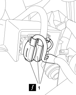
1. Disconnect the electrical connections for pressure sensors (1a) and temperature (1b) for the particulate filter
| Description | Connector | |
|---|---|---|
| 1a | DIFFERENTIAL PRESSURE SENSOR FAP | See K187 FAP DIFFERENTIAL PRESSURE SENSOR |
| Description | Connector | |
|---|---|---|
| 1b | DOWNSTREAM PARTICLE FILTER (DPF) TEMPERATURE SENSOR | See K190 DOWNSTREAM PARTICULATE FILTER TEMPERATURE SENSOR (DPF) |
- THE FOLLOWING OPERATIONS ARE VALID FOR ALL VERSIONS.
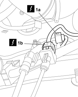
1. - Disconnect the electrical connection for the front crash sensor.
| Description | Connector | |
|---|---|---|
| 1 | AIR BAG FRONT SENSOR | See K039 FRONT AIR BAG SENSOR |
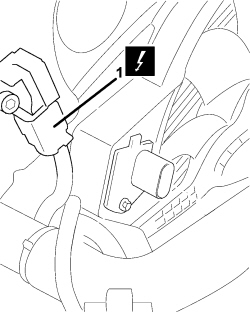
1. Disconnect the electrical connections for brake liquid level sensor (1a) and ABS control unit (1b).
| Description | Connector | |
|---|---|---|
| 1a | BRAKE FLUID LEVEL SENSOR (SWITCH) | See K025 BRAKE FLUID LEVEL SENSOR (SWITCH) |
| Description | Connector | |
|---|---|---|
| 1b | BRAKING SYTEM CONTROL UNIT | See M051 Braking system control unit |
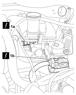
1. Disconnect the electrical connection for the reversing switch.
| Description | Connector | |
|---|---|---|
| 1 | REVERSING LIGHTS SWITCH | See I020 REVERSING LIGHTS SWITCH |
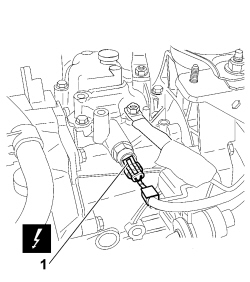
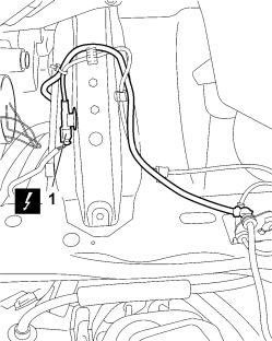
- Operate both wheel rpm sensors:
1. Disconnect the electrical connection for the front wheel rpm sensors.
| Description | Connector | |
|---|---|---|
| 1 | LEFT FRONT WHEEL SENSOR FOR ABS | See K070 LEFT FRONT WHEEL SENSOR FOR ABS |
| Description | Connector | |
|---|---|---|
| 1 | RIGHT FRONT WHEEL SENSOR FOR ABS | See K071 RIGHT FRONT WHEEL SENSOR FOR ABS |
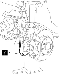
1. Disconnect the electrical connection for the brake pad wear sensor.
| Description | Connector | |
|---|---|---|
| 1 | LEFT BRAKE PAD WEAR SENSOR (SWITCH) | See K020 LEFT BRAKE PAD WEAR SENSOR (SWITCH) |
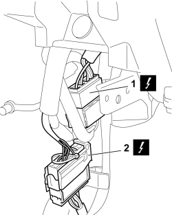
- Work on both sides of the vehicle:
1. Disconnect the electrical connections for the door wiring.
| Description | Connector | |
|---|---|---|
| 1 | LEFT FRONT DOOR COUPLING | See D030 DRIVER'S FRONT DOOR COUPLING |
| Description | Connector | |
|---|---|---|
| 1 | RIGHT FRONT DOOR COUPLING | See D031 PASSENGER FRONT DOOR COUPLING |
2. Disconnect the rear couplings to the dashboard crossmember wiring.
| Description | Connector | |
|---|---|---|
| 2 | FRONT/DASHBOARD COUPLING | See D001 FRONT/DASHBOARD COUPLING |
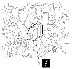
- THE FOLLOWING OPERATIONS ARE SPECIFICALLY FOR PETROL VERSIONS
1. Disconnect the electrical connection for the coupling to the engine wiring.
| Description | Connector | |
|---|---|---|
| 1 | FRONT/ENGINE COUPLING | See D004 FRONT/ENGINE COUPLING |
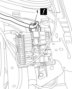
- THE FOLLOWING OPERATIONS ARE SPECIFICALLY FOR 1.3 Multijet VERSIONS
1. Disconnect the electrical connection for the coupling to the engine wiring.
| Description | Connector | |
|---|---|---|
| 1 | FRONT/ENGINE COUPLING | See D004 FRONT/ENGINE COUPLING |
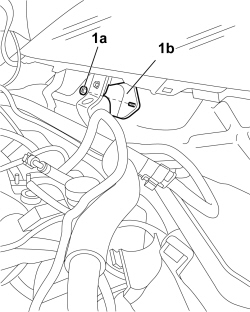
- THE FOLLOWING OPERATIONS ARE VALID FOR ALL VERSIONS.
1. Undo nuts (1a) and remove bulkhead coupling protection (1b).
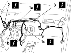
1. Disconnect the electrical connections for brake pedal switches (1a), clutch (1b) and accelerator potentiometer (1c).
| Description | Connector | |
|---|---|---|
| 1a | BRAKE PEDAL SWITCH | See I030 BRAKE PEDAL SWITCH |
| Description | Connector | |
|---|---|---|
| 1b | CLUTCH PEDAL SWITCH | See I031 CLUTCH PEDAL SWITCH |
| Description | Connector | |
|---|---|---|
| 1c | ACCELERATOR PEDAL POTENTIOMETER | See K055 ACCELERATOR PEDAL POTENTIOMETER |
- Undo the earth spots arranged on the wiring and disengage the wiring from retainers.
2. Disconnect the electrical connection for the passenger compartment wiring coupling.
| Description | Connector | |
|---|---|---|
| 2 | FRONT/REAR COUPLING | See D006 FRONT/REAR COUPLING |
3. Disengage bulkhead hole seal between the engine compartment and passenger compartment, then remove the engine compartment wiring.
Refitting
- Check that the engine compartment wiring is not damaged and that the individual conductors are correctly fastened to the connections.
- If necessary, carry out continuity tests.
- Place the engine compartment wiring in position, inserting it via the opening on the engine compartment side.
- Fit the bulkhead coupling in place and attach the retainers.
1. Connect the electrical connections for brake pedal switches (1a), clutch (1b) and accelerator potentiometer (1c).
| Description | Connector | |
|---|---|---|
| 1a | BRAKE PEDAL SWITCH | See I030 BRAKE PEDAL SWITCH |
| Description | Connector | |
|---|---|---|
| 1b | CLUTCH PEDAL SWITCH | See I031 CLUTCH PEDAL SWITCH |
| Description | Connector | |
|---|---|---|
| 1c | ACCELERATOR PEDAL POTENTIOMETER | See K055 ACCELERATOR PEDAL POTENTIOMETER |
2. Connect the electrical connection for the coupling to the passenger compartment wiring.
| Description | Connector | |
|---|---|---|
| 2 | FRONT/REAR COUPLING | See D006 FRONT/REAR COUPLING |
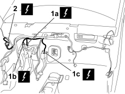
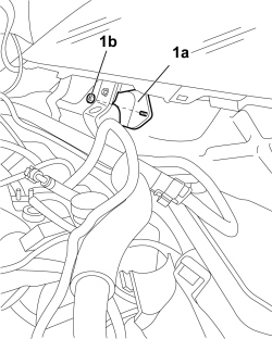
1. Position bulkhead coupling protection (1a) and tighten nuts (1b)
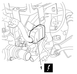
- THE FOLLOWING OPERATIONS ARE SPECIFICALLY FOR PETROL VERSIONS
1. Connect the electrical connection for the coupling to the engine wiring.
| Description | Connector | |
|---|---|---|
| 1 | FRONT/ENGINE COUPLING | See D004 FRONT/ENGINE COUPLING |
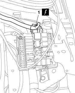
- THE FOLLOWING OPERATIONS ARE SPECIFICALLY FOR 1.3 Multijet VERSIONS
1. Connect the electrical connection for the coupling to the engine wiring.
| Description | Connector | |
|---|---|---|
| 1 | FRONT/ENGINE COUPLING | See D004 FRONT/ENGINE COUPLING |
- THE FOLLOWING OPERATIONS ARE VALID FOR ALL VERSIONS.
- Work on both sides of the vehicle:
1. Connect the electrical connections for the door wiring.
| Description | Connector | |
|---|---|---|
| 1 | LEFT FRONT DOOR COUPLING | See D030 DRIVER'S FRONT DOOR COUPLING |
| Description | Connector | |
|---|---|---|
| 1 | RIGHT FRONT DOOR COUPLING | See D031 PASSENGER FRONT DOOR COUPLING |
2. Connect the rear couplings to the dashboard crossmember wiring.
| Description | Connector | |
|---|---|---|
| 2 | FRONT/DASHBOARD COUPLING | See D001 FRONT/DASHBOARD COUPLING |
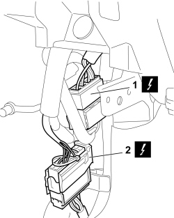
1. Connect the electrical connection for the brake pad wear sensor.
| Description | Connector | |
|---|---|---|
| 1 | LEFT BRAKE PAD WEAR SENSOR (SWITCH) | See K020 LEFT BRAKE PAD WEAR SENSOR (SWITCH) |
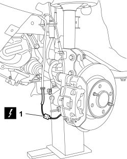
- Operate both wheel rpm sensor connections:
1. Connect the electrical connection for the front wheel rpm sensor.
| Description | Connector | |
|---|---|---|
| 1 | LEFT FRONT WHEEL SENSOR FOR ABS | See K070 LEFT FRONT WHEEL SENSOR FOR ABS |
| Description | Connector | |
|---|---|---|
| 1 | RIGHT FRONT WHEEL SENSOR FOR ABS | See K071 RIGHT FRONT WHEEL SENSOR FOR ABS |
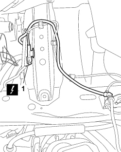
1. Connect the electrical connection for the reversing switch.
| Description | Connector | |
|---|---|---|
| 1 | REVERSING LIGHTS SWITCH | See I020 REVERSING LIGHTS SWITCH |
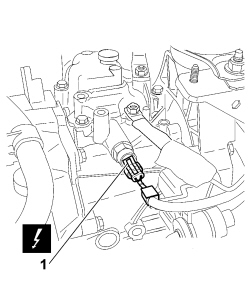
1. Connect the electrical connections for brake liquid level sensor (1a) and ABS control unit (1b).
| Description | Connector | |
|---|---|---|
| 1a | BRAKE FLUID LEVEL SENSOR (SWITCH) | See K025 BRAKE FLUID LEVEL SENSOR (SWITCH) |
| Description | Connector | |
|---|---|---|
| 1b | BRAKING SYSTEM CONTROL UNIT | See M051 Braking system control unit |
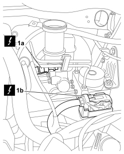
1. Connect the electrical connection for the front crash sensor.
| Description | Connector | |
|---|---|---|
| 1 | AIR BAG FRONT SENSOR | See K039 FRONT AIR BAG SENSOR |
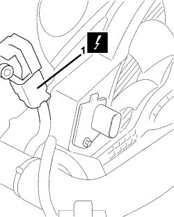
- THE FOLLOWING OPERATIONS ARE SPECIFICALLY FOR 1.3 Multijet VERSIONS
1. Connect the electrical connections for pressure sensor (1a) and temperature sensor (1b) for the particulate filter
| Description | Connector | |
|---|---|---|
| 1a | DIFFERENTIAL PRESSURE SENSOR FAP | See K187 FAP DIFFERENTIAL PRESSURE SENSOR |
| Description | Connector | |
|---|---|---|
| 1b | DOWNSTREAM PARTICLE FILTER (DPF) TEMPERATURE SENSOR | See K190 DOWNSTREAM PARTICULATE FILTER TEMPERATURE SENSOR (DPF) |
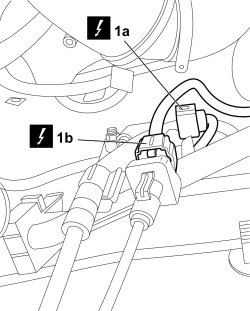
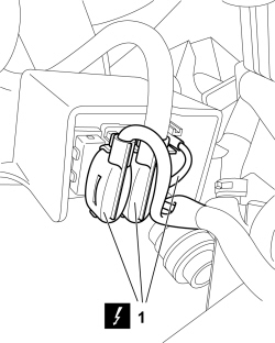
1. Connect the electrical connections for the heater plugs control unit.
| Description | Connector | |
|---|---|---|
| 1 | GLOW PLUG PREHEATING CONTROL UNIT | See M015 PLUG PREHEATING CONTROL UNIT |
- THE FOLLOWING OPERATIONS ARE VALID FOR ALL VERSIONS.
1. Connect the electrical connection for the windscreen washer pump.
| Description | Connector | |
|---|---|---|
| 1 | WINDSCREEN/REARSCREEN ELECTRIC WASHER PUMP MOTOR | See N022 WINDSCREEN WASHER/ REAR WINDOW WASHER PUMP MOTOR |
2. Connect the electrical connection for the linear pressure switch.
| Description | Connector | |
|---|---|---|
| 2 | LINEAR SENSOR FOR FANS | See K120 LINEAR SENSOR FOR FANS |
1. Connect the electrical connection for the horn.
| Description | Connector | |
|---|---|---|
| 1 | SINGLE-TONE HORN | See P005 SINGLE-TONE HORN |
1. Connect the electrical connection for the engine cooling fan.
| Description | Connector | |
|---|---|---|
| 1 | ENGINE FAN MOTOR | See N011 FAN MOTOR |
1. Connect the electrical connection to the engine cooling fan adjustment rheostat.
| Description | Connector | |
|---|---|---|
| 1 | ENGINE FAN ADJUSTMENT HEATING COIL - 1 | See O010 ENGINE FAN ADJUSTMENT RESISTANCE - 1 |
- Secure the engine compartment wiring with the retaining clips on the passenger compartment bulkhead and tighten the bands.
Op. 7210A74 R R FACIA SUPPORT BEAM
Op. 5010C55 RIGHT LOWER AIR DIFFUSER - R+R
Op. 4110D20 STEERING ELECTRICAL CONTROL DEVICE - R R
- Fit both front pillar trims:
Op. 7040H30 FRONT PILLAR TRIM (ONE), LEFT OR RIGHT - R.R.
Op. 7040A10 DASHBOARD TRIM - R+R
- Fit both side doors.
Op. 7210E36 R.R. FRONT SIDE DOOR
- Fit both diffusers:
Op. 5010C26 FRONT SIDE PANEL AIR DIFFUSER, L.H. OR R.H. - R R
Op. 5010C12 WINDSCREEN DEMISTER DIFFUSER - R+R
Op. 5010C30 CENTRAL AIR VENT IN DASHBOARD - R.R.
Op. 5570T80 CAR RADIO EQUIPMENT - R+R
Op. 7040A44 LEFT DASHBOARD SIDE TRIM - R.R.
Op. 7040A49 CONNECTOR HOLDER TRIM FOR EOBD - R.R.
Op. 7040A41 SPEAKER GRILLE (ONE) LH OR RH ON INSTRUMENT FACIA - R R
Op. 7040A56 SWITCH UNIT IN DASHBOARD - R.R.
- Fit both electric window switches:
Op. 7005M10 ELECTRIC WINDOW CONTROL SWITCH (ONE) FOR ONE FRONT DOOR - R.R.
- Fit both centre console side trims:
Op. 7040A65 CONSOLE SIDE CLOSING (ONE) - R.R.
Op. 7040A28 TRIM ON GEARBOX CONTROL PANEL - R.R.
Op. 2125C02 GEAR CONTROL LEVER OUTER BOOT - R.R.
Op. 2125C24 GEAR LEVER KNOB - R + R
Op. 5560B10 CONTROL PANEL - R+R
Op. 7040A23 INSTRUMENT PANEL FRAME IN DASHBOARD - R.R
Op. 5550A10 STALK UNIT ASSEMBLY - R+R
Op. 4110A10 STEERING WHEEL - R+R FOR REPLACEMENT OR CHECKS
Op. 5580C18 AIR BAG MODULE - R+R
Op. 5580E08 AERIAL FOR ELECTRONIC KEY (CODE) - R.R
Op. 7040A26 STEERING COLUMN TRIM - R+R
Op. 7040A30
- If the vehicle is provided with a knee protection Air Bag
Op. 5580C23 DRIVER'S KNEE BAG - R.R.
Op. 7040H10 ROOF PANEL LINING - R.R.
- Fit both upper elements of the centre pillar covers.
Op. 7040H38 CENTRE PILLAR UPPER ELEMENT (ONE), LEFT OR RIGHT - R.R
Op. 7040E10 FRONT COURTESY LIGHT - R+R
- Fit both the sun blinds
Op. 7065C34 SUN BLIND (ONE), LEFT OR RIGHT - R.R.
- Fit both front pillar trims.
Op. 7040H30 FRONT PILLAR TRIM (ONE), LEFT OR RIGHT - R.R.
Op. 7055B66 ENGINE COMPARTMENT DUST COVER IN RIGHT FRONT WHEEL ARCH - R.R.
Op. 4410D22 BRACKET FIXING FRONT SUSPENSION CROSSMEMBER TO BODYSHELL (ONE), LEFT OR RIGHT - R.R.
Op. 4450B12 FRONT WHEELS (TWO) - R+R
Op. 5050B42 WINDSCREEN WIPER MOTOR - R+R
Op. 7210E22 R.R. WINDSCREEN BASE TRIM
Op. 5050B34 WINDSCREEN WIPER ARM/S COMPLETE WITH BLADE - R+R
Op. 5010A12 HEATER WATER SUPPLY PIPE - R.R.
- THE FOLLOWING OPERATIONS ARE SPECIFICALLY FOR 1.3 Multijet VERSIONS
Op. 1048B44 RIGID AIR SUPPLY PIPE BETWEEN HEAT EXCHANGER AND INTAKE MANIFOLD - R.R.
- THE FOLLOWING OPERATIONS ARE VALID FOR ALL VERSIONS.
Op. 5530B52 BATTERY SUPPORT/DRIP TRAY - R.R
- THE FOLLOWING OPERATIONS ARE SPECIFICALLY FOR 1.3 Multijet VERSIONS
Op. 1044B10 FUEL FILTER ASSEMBLY - R + R OR REPLACE
- THE FOLLOWING OPERATIONS ARE VALID FOR ALL VERSIONS.
Op. 1048A10 AIR FILTER ASSEMBLY - R.R.
Op. 1048A23 COLD AIR INTAKE FOR AIR FILTER - R.R
Op. 0010T20 ENGINE COOLANT - CHANGE
Op. 0010T84 COOLANT FOR AIR CONDITIONING SYSTEM - DEHYDRATE AND REPRESSURIZE
- Connect the battery terminals.
| Description | Connector | |
|---|---|---|
| BATTERY | See A001 BATTERY |
- Remove the vehicle from the lift-
Parts & tools for this job For 2007 Fiat 500
- TOOLDigital multimeterSearch: automotive digital multimeter
- PARTAssorted fuse kitSearch: car fuse assortment kit
- TOOLWire crimper and connector kitSearch: wire crimper connector kit
Links open Amazon search results in a new tab. As an Amazon Associate I earn from qualifying purchases.