
R r facia support beam
- Make
- Fiat
- Model
- 500 Factory Service Manual
- Year
- 2007–2024
- Section
- Removing-refitting › R r facia support beam
R R FACIA SUPPORT BEAM
Removing
Before working on the Air Bag system, follow the safety instructions for working on the system very carefully.
- Disconnect the negative battery terminal.
| Description | Connector | |
|---|---|---|
| Battery | See A001 BATTERY |
- Remove both running board connections
Op. 7040L42
- Remove both front doors.
Op. 7210E36 R.R. FRONT SIDE DOOR
- For vehicles fitted with a knee air bag carry out the following procedure:
Op. 5580C23 DRIVER'S KNEE BAG - R.R.
- For vehicles not fitted a knee air bag carry out the following procedure:
Op. 7040A30
- For all vehicles carry out the following procedure:
Op. 7040A26 STEERING COLUMN TRIM - R+R
Op. 5580E08 AERIAL FOR ELECTRONIC KEY (CODE) - R.R
Op. 5580C18 AIR BAG MODULE - R+R
Op. 4110A10 STEERING WHEEL - R+R FOR REPLACEMENT OR CHECKS
Op. 5550A10 STALK UNIT ASSEMBLY - R+R
Op. 7040A23 INSTRUMENT PANEL FRAME IN DASHBOARD - R.R
Op. 5560B10 CONTROL PANEL - R+R
Op. 5520A14 IGNITION KEY LOCK BARREL - R+R
Op. 2125C24 GEAR LEVER KNOB - R + R
Op. 2125C02 GEAR CONTROL LEVER OUTER BOOT - R.R.
Op. 7040A28 TRIM ON GEARBOX CONTROL PANEL - R.R.
- Remove both centre console side trims.
Op. 7040A65 CONSOLE SIDE CLOSING (ONE) - R.R.
- Remove both electronic window switches:
Op. 7005M10 ELECTRIC WINDOW CONTROL SWITCH (ONE) FOR ONE FRONT DOOR - R.R.
Op. 7040L20 TUNNEL COVER - R.R
Op. 7040A56 SWITCH UNIT IN DASHBOARD - R.R.
Op. 7040A41 SPEAKER GRILLE (ONE) LH OR RH ON INSTRUMENT FACIA - R R
Op. 7040A49 CONNECTOR HOLDER TRIM FOR EOBD - R.R.
Op. 7040A44 LEFT DASHBOARD SIDE TRIM - R.R.
Op. 5570T80 CAR RADIO EQUIPMENT - R+R
Op. 5010C30 CENTRAL AIR VENT IN DASHBOARD - R.R.
Op. 5010C12 WINDSCREEN DEMISTER DIFFUSER - R+R
- Remove both diffusers:
Op. 5010C26 FRONT SIDE PANEL AIR DIFFUSER, L.H. OR R.H. - R R
Op. 7040A10 DASHBOARD TRIM - R+R
- Remove both pillar trims.
Op. 7040H30 FRONT PILLAR TRIM (ONE), LEFT OR RIGHT - R.R.
Op. 1048A23 COLD AIR INTAKE FOR AIR FILTER - R.R
Op. 1048A10 AIR FILTER ASSEMBLY - R.R.
Op. 0010T20 ENGINE COOLANT - CHANGE
Op. 5530B52 BATTERY SUPPORT/DRIP TRAY - R.R
Op. 5010A12 HEATER WATER SUPPLY PIPE - R.R.
- Position a suitable container for collecting the coolant.
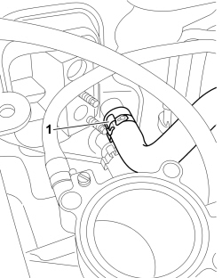
1. Open the retaining band and disconnect the heater water return pipe, heater side.
Op. 0010T84 COOLANT FOR AIR CONDITIONING SYSTEM - DEHYDRATE AND REPRESSURIZE
Op. 1056B15 THROTTLE BODY INTERGRAL WITH MDS - R.R.
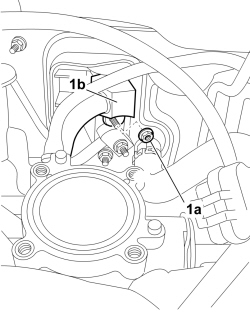
1. Undo nut (1a) from pipe (1b), expansion valve side.
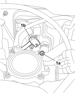
1. Undo nut (1a) and disconnect pipe (1b), expansion valve side.
Seal the connectors that have been disconnected using suitable plugs to prevent dampness and impurities from entering the system.
Op. 4110D20 STEERING ELECTRICAL CONTROL DEVICE - R R
Op. 5010C55 RIGHT LOWER AIR DIFFUSER - R+R
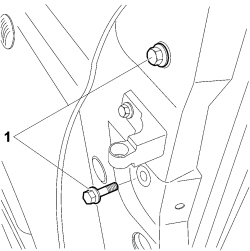
1. On both sides, undo the bolts securing the crossmember.
1. Detach the electrical connection for the front door coupling.
| Description | Connector | |
|---|---|---|
| 1 | Dashboard/rear coupling | See D020 DASHBOARD/REAR COUPLING |
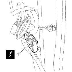
- Disconnect the aerial.
| Description | Connector | |
|---|---|---|
| Coaxial cable for radio aerial coupling | See D168 COAXIAL CABLE FOR RADIO AERIAL COUPLING |
1. Detach the electrical connection.
| Description | Connector | |
|---|---|---|
| 1 | Dashboard braid coupling | See D259 INSTRUMENT PANEL BRIDGE COUPLING |
2. Disconnect the connection for the Air Bag control unit.
| Description | Connector | |
|---|---|---|
| 2 | Air Bag control unit | See M060 AIR BAG CONTROL UNIT |
3. Undo nut (3a) and disconnect earth connection (3b).
| Description | Connector | |
|---|---|---|
| 3b | Air Bag system earth | See C050 AIR BAG SYSTEM EARTH |
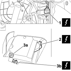
1. Detach the electrical connection.
| Description | Connector | |
|---|---|---|
| 1 | Front/dashboard coupling | See D001 FRONT/DASHBOARD COUPLING |
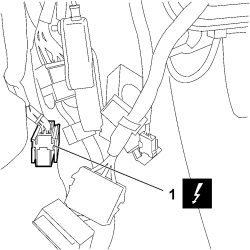
1. Undo nut (1a) and disconnect earth connection (1b).
| Description | Connector | |
|---|---|---|
| 1b | Driver''s dashboard earth | See C015 DASHBOARD EARTH, DRIVER'S SIDE |
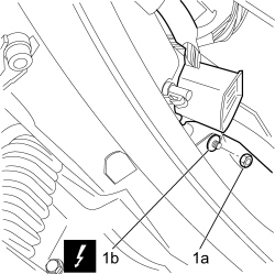
1. Disconnect the Body Computer electrical connections.
| Description | Connector | |
|---|---|---|
| 1 | Body computer | See M001 BODY COMPUTER |
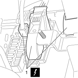
1. Unscrew nuts (1a) and bolt (1b) securing the gearbox lever mount.
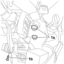
1. Unscrew the bolts securing the gear lever support bracket.
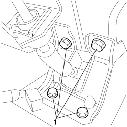
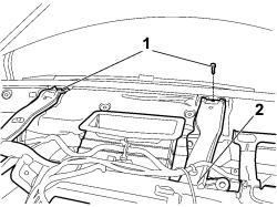
1. Undo the bolts on the windscreen base.
2. Remove the entire air conditioning unit crossmember.
Refitting
- Place the entire air conditioning unit crossmember in position.
- Tighten the bolts on the windscreen base.
- Tighten the bolts securing the gearbox lever support bracket.
- Tighten the bolts securing the gearbox lever support.
- Tighten the nuts securing the gearbox lever support.
1. Connect the Body computer electrical connections.
| Description | Connector | |
|---|---|---|
| 1 | Body computer | See M001 BODY COMPUTER |
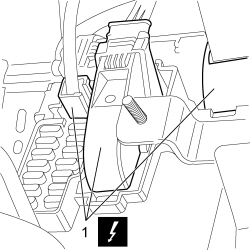
1. Secure the electrical connection.
| Description | Connector | |
|---|---|---|
| 1 | Front/dashboard coupling | See D001 FRONT/DASHBOARD COUPLING |
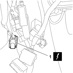
1. Connect earth connection (1a) and tighten nut (1b).
| Description | Connector | |
|---|---|---|
| 1 | Driver''s dashboard earth | See C015 DASHBOARD EARTH, DRIVER'S SIDE |
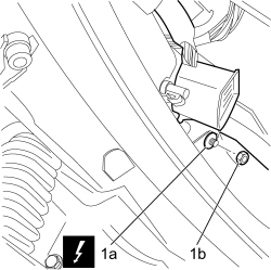
1. Secure the electrical connection.
| Description | Connector | |
|---|---|---|
| 1 | Dashboard braid coupling | See D259 INSTRUMENT PANEL BRIDGE COUPLING |
2. Connect the connection for the Air Bag control unit.
| Description | Connector | |
|---|---|---|
| 2 | Air Bag control unit | See M060 AIR BAG CONTROL UNIT |
3. Connect earth connection (3a) and tighten nut (3b).
| Description | Connector | |
|---|---|---|
| 3a | Air Bag system earth | See C050 AIR BAG SYSTEM EARTH |
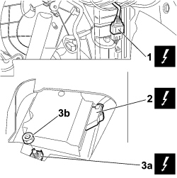
1. Secure the electrical connection.
| Description | Connector | |
|---|---|---|
| Dashboard/rear coupling | See D020 DASHBOARD/REAR COUPLING |
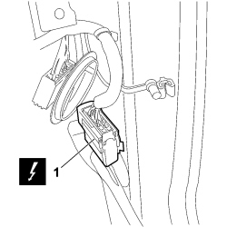
- Connect the aerial.
| Description | Connector | |
|---|---|---|
| Coaxial cable for radio aerial coupling | See D168 COAXIAL CABLE FOR RADIO AERIAL COUPLING |
1. Tighten the bolts securing the crossmember on both sides to the recommended torque.
| Component | Fastening | dia | Value (daNm) | Validity |
|---|---|---|---|---|
| Instrument panel (on side panels) | Bolt | M8 | 2.0 | all versions |
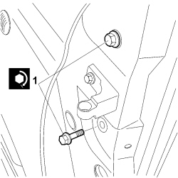
Op. 5010C55 RIGHT LOWER AIR DIFFUSER - R+R
Op. 4110D20 STEERING ELECTRICAL CONTROL DEVICE - R R
- Remove the protective caps from the rigid air conditioning coolant hose.
- Replace the O-rings from the rigid air conditioning coolant hose connectors using rings resistant to R134A coolant.
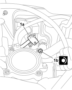
1. Connect pipe (1a) to the expansion valve and tighten nut (1b) to the recommended torque.
| Component | Fastening | dia | Value (daNm) | Validity |
|---|---|---|---|---|
| Supply/return pipes (on condenser) | Bolt | M8 | 2.0 | all versions |
1. Connect pipe (1a), expansion valve side, and tighten nut (1b) to the recommended torque.
| Component | Fastening | dia | Value (daNm) | Validity |
|---|---|---|---|---|
| Supply/return pipes (on condenser) | Bolt | M8 | 2.0 | all versions |
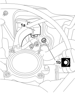
Op. 0010T84 COOLANT FOR AIR CONDITIONING SYSTEM - DEHYDRATE AND REPRESSURIZE
Op. 1056B15 THROTTLE BODY INTERGRAL WITH MDS - R.R.
- Connect the heater water return pipe, heater side and close the retaining band.
Op. 5010A12 HEATER WATER SUPPLY PIPE - R.R.
Op. 5530B52 BATTERY SUPPORT/DRIP TRAY - R.R
Op. 0010T20 ENGINE COOLANT - CHANGE
Op. 1048A10 AIR FILTER ASSEMBLY - R.R.
Op. 1048A23 COLD AIR INTAKE FOR AIR FILTER - R.R
- Remove both pillar trims.
Op. 7040H30 FRONT PILLAR TRIM (ONE), LEFT OR RIGHT - R.R.
Op. 7040A10 DASHBOARD TRIM - R+R
- Remove both diffusers:
Op. 5010C26 FRONT SIDE PANEL AIR DIFFUSER, L.H. OR R.H. - R R
Op. 5010C12 WINDSCREEN DEMISTER DIFFUSER - R+R
Op. 5010C30 CENTRAL AIR VENT IN DASHBOARD - R.R.
Op. 5570T80 CAR RADIO EQUIPMENT - R+R
Op. 7040A44 LEFT DASHBOARD SIDE TRIM - R.R.
Op. 7040A49 CONNECTOR HOLDER TRIM FOR EOBD - R.R.
Op. 7040A41 SPEAKER GRILLE (ONE) LH OR RH ON INSTRUMENT FACIA - R R
Op. 7040A56 SWITCH UNIT IN DASHBOARD - R.R.
Op. 7040L20 TUNNEL COVER - R.R
- Remove both electronic window switches:
Op. 7005M10 ELECTRIC WINDOW CONTROL SWITCH (ONE) FOR ONE FRONT DOOR - R.R.
- Remove both centre console side trims:
Op. 7040A65 CONSOLE SIDE CLOSING (ONE) - R.R.
Op. 7040A28 TRIM ON GEARBOX CONTROL PANEL - R.R.
Op. 2125C02 GEAR CONTROL LEVER OUTER BOOT - R.R.
Op. 2125C24 GEAR LEVER KNOB - R + R
Op. 5520A14 IGNITION KEY LOCK BARREL - R+R
Op. 5560B10 CONTROL PANEL - R+R
Op. 7040A23 INSTRUMENT PANEL FRAME IN DASHBOARD - R.R
Op. 5550A10 STALK UNIT ASSEMBLY - R+R
Op. 4110A10 STEERING WHEEL - R+R FOR REPLACEMENT OR CHECKS
Op. 5580C18 AIR BAG MODULE - R+R
Op. 5580E08 AERIAL FOR ELECTRONIC KEY (CODE) - R.R
Op. 7040A26 STEERING COLUMN TRIM - R+R
- For vehicles fitted with a knee air bag carry out the following procedure:
Op. 5580C23 DRIVER'S KNEE BAG - R.R.
- For vehicles not fitted a knee air bag carry out the following procedure:
Op. 7040A30
- Refit both front doors.
Op. 7210E36 R.R. FRONT SIDE DOOR
- Refit both running board connections
Op. 7040L42
Op. 0010T21 ENGINE COOLANT - CHECK DENSITY AND TOP UP, IF NECESSARY
- Connect the negative battery terminal.
| Description | Connector | |
|---|---|---|
| Battery | See A001 BATTERY |
Removing
Before working on the Air Bag system, follow the safety instructions for working on the system very carefully.
- Disconnect the negative battery terminal.
| Description | Connector | |
|---|---|---|
| Battery | See A001 BATTERY |
- Remove both running board connectors.
Op. 7040L42
- Remove both the front doors:
Op. 7210E36 R.R. FRONT SIDE DOOR
- For vehicles with knee Air Bag carry out the following operation:
Op. 5580C23 DRIVER'S KNEE BAG - R.R.
- For vehicles without knee Air Bag carry out the following operation:
Op. 7040A30
- For all vehicles carry out the following operations:
Op. 7040A26 STEERING COLUMN TRIM - R+R
Op. 5580E08 AERIAL FOR ELECTRONIC KEY (CODE) - R.R
Op. 5580C18 AIR BAG MODULE - R+R
Op. 4110A10 STEERING WHEEL - R+R FOR REPLACEMENT OR CHECKS
Op. 5550A10 STALK UNIT ASSEMBLY - R+R
Op. 7040A23 INSTRUMENT PANEL FRAME IN DASHBOARD - R.R
Op. 5560B10 CONTROL PANEL - R+R
Op. 5520A14 IGNITION KEY LOCK BARREL - R+R
Op. 2125C24 GEAR LEVER KNOB - R + R
Op. 2125C02 GEAR CONTROL LEVER OUTER BOOT - R.R.
Op. 7040A28 TRIM ON GEARBOX CONTROL PANEL - R.R.
- Remove both centre console side trims:
Op. 7040A65 CONSOLE SIDE CLOSING (ONE) - R.R.
- Remove both the electric window switches:
Op. 7005M10 ELECTRIC WINDOW CONTROL SWITCH (ONE) FOR ONE FRONT DOOR - R.R.
Op. 7040L20 TUNNEL COVER - R.R
Op. 7040A56 SWITCH UNIT IN DASHBOARD - R.R.
Op. 7040A41 SPEAKER GRILLE (ONE) LH OR RH ON INSTRUMENT FACIA - R R
Op. 7040A49 CONNECTOR HOLDER TRIM FOR EOBD - R.R.
Op. 7040A44 LEFT DASHBOARD SIDE TRIM - R.R.
Op. 5570T80 CAR RADIO EQUIPMENT - R+R
Op. 5010C30 CENTRAL AIR VENT IN DASHBOARD - R.R.
Op. 5010C12 WINDSCREEN DEMISTER DIFFUSER - R+R
- Remove both diffusers:
Op. 5010C26 FRONT SIDE PANEL AIR DIFFUSER, L.H. OR R.H. - R R
Op. 7040A10 DASHBOARD TRIM - R+R
Op. 1048A23 COLD AIR INTAKE FOR AIR FILTER - R.R
Op. 1048A10 AIR FILTER ASSEMBLY - R.R.
Op. 1048B44 RIGID AIR SUPPLY PIPE BETWEEN HEAT EXCHANGER AND INTAKE MANIFOLD - R.R.
Op. 5530B52 BATTERY SUPPORT/DRIP TRAY - R.R
Op. 5010A12 HEATER WATER SUPPLY PIPE - R.R.
- Position a suitable container for collecting the coolant.
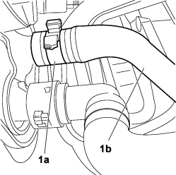
1. Open securing band (1a) and disconnect return pipe (1b).
Op. 0010T84 COOLANT FOR AIR CONDITIONING SYSTEM - DEHYDRATE AND REPRESSURIZE
Op. 1056B15 THROTTLE BODY INTERGRAL WITH MDS - R.R.
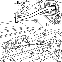
1. Undo nut (1a) from pipe (1b), expansion valve side.
2. Release the pipe from the retaining clip.
Seal the connectors that have been disconnected using suitable plugs to prevent dampness and impurities from entering the system.
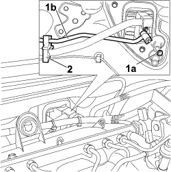
1. Undo nut (1a) and disconnect pipe (1b), expansion valve side.
2. Release the pipe from the retaining clip.
Seal the connectors that have been disconnected using suitable plugs to prevent dampness and impurities from entering the system.
Op. 4110D20 STEERING ELECTRICAL CONTROL DEVICE - R R
Op. 5010C55 RIGHT LOWER AIR DIFFUSER - R+R
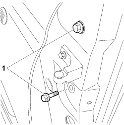
1. Unscrew the bolts securing the crossmember on both sides.
1. Detach the electrical connection.
| Description | Connector | |
|---|---|---|
| 1 | Dashboard/rear coupling | See D020 DASHBOARD/REAR COUPLING |
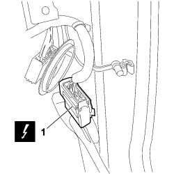
- Disconnect the aerial.
| Description | Connector | |
|---|---|---|
| Coaxial cable for radio aerial coupling | See D168 COAXIAL CABLE FOR RADIO AERIAL COUPLING |
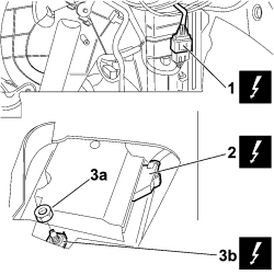
1. Detach the electrical connection.
| Description | Connector | |
|---|---|---|
| 1 | Dashboard braid junction | See D259 INSTRUMENT PANEL BRIDGE COUPLING |
2. Disconnect the electrical connection for the Air Bag control unit.
| Description | Connector | |
|---|---|---|
| 2 | Air Bag control unit | See M060 AIR BAG CONTROL UNIT |
3. Undo nut (3a) and disconnect earth connection (3b).
| Description | Connector | |
|---|---|---|
| 3b | Air Bag system earth | See C050 AIR BAG SYSTEM EARTH |
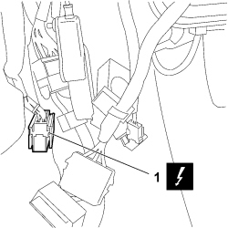
1. Detach the electrical connection.
| Description | Connector | |
|---|---|---|
| 1 | Front/dashboard coupling | See D001 FRONT/DASHBOARD COUPLING |
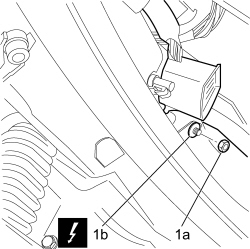
1. Undo nut (1a) and disconnect earth connection (1b).
| Description | Connector | |
|---|---|---|
| 1 | Driver''s dashboard earth | See C015 DASHBOARD EARTH, DRIVER'S SIDE |
1. Disconnect the Body Computer electrical connections.
| Description | Connector | |
|---|---|---|
| 1 | Body computer | See M001 BODY COMPUTER |
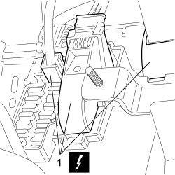
1. Unscrew nuts (1a) and bolt (1b) securing the gearbox lever mount.
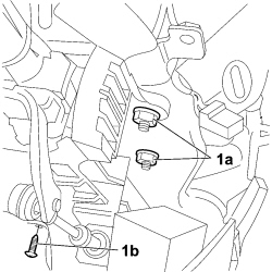
1. Unscrew the bolts securing the gear lever mount bracket.
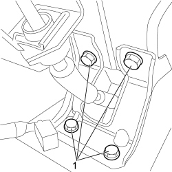
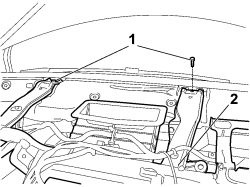
1. Undo the bolts on the windscreen base.
2. Remove the cross member complete with air conditioning unit.
Refitting
- Position the cross member in its housing complete with air conditioning unit.
- Tighten the bolts on the windscreen base.
- Tighten the bolts securing the gear lever mount bracket.
- Tighten the bolt securing the gear lever support.
- Tighten the nuts securing the gear lever support.
1. Connect the Body Computer electrical connections.
| Description | Connector | |
|---|---|---|
| 1 | Body computer | See M001 BODY COMPUTER |
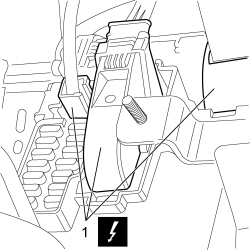
1. Secure the electrical connection.
| Description | Connector | |
|---|---|---|
| 1 | Front/dashboard coupling | See D001 FRONT/DASHBOARD COUPLING |
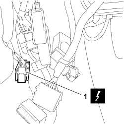
1. Connect earth connection (1a) and tighten nut (1b).
| Description | Connector | |
|---|---|---|
| 1a | Driver''s dashboard earth | See C015 DASHBOARD EARTH, DRIVER'S SIDE |
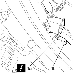
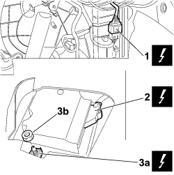
1. Secure the electrical connection.
| Description | Connector | |
|---|---|---|
| 1 | Dashboard braid junction | See D259 INSTRUMENT PANEL BRIDGE COUPLING |
2. Connect the connection for the Air Bag control unit.
| Description | Connector | |
|---|---|---|
| 2 | Air Bag control unit | See M060 AIR BAG CONTROL UNIT |
3. Connect earth connection (3a) and tighten nut (3b).
| Description | Connector | |
|---|---|---|
| 3a | Air Bag system earth | See C050 AIR BAG SYSTEM EARTH |
1. Secure the electrical connection.
| Description | Connector | |
|---|---|---|
| 1 | Dashboard/rear coupling | See D020 DASHBOARD/REAR COUPLING |
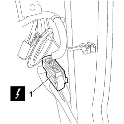
- Connect the aerial.
| Description | Connector | |
|---|---|---|
| Coaxial cable for radio aerial coupling | See D168 COAXIAL CABLE FOR RADIO AERIAL COUPLING |
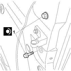
1. Tighten the bolts securing the cross member on both sides to the recommended torque.
| Component | Fastening | dia | Value (daNm) | Validity |
|---|---|---|---|---|
| Instrument panel (on side panels) | Bolt | M8 | 2.0 | all versions |
Op. 5010C55 RIGHT LOWER AIR DIFFUSER - R+R
Op. 4110D20 STEERING ELECTRICAL CONTROL DEVICE - R R
- Remove the protective caps from the air conditioner coolant rigid pipes.
- Replace the O-rings for the connector on the air conditioner coolant rigid pipes, using rings that are resistant to R134A refrigerant fluid.
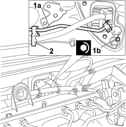
1. Secure the pipe to the retaining clip.
2. Connect pipe (2a) to the expansion valve and tighten nut (2b) to the specified torque.
| Component | Fastening | dia | Value (daNm) | Validity |
|---|---|---|---|---|
| Supply/return pipes (on expansion valve) | Nut | M10x1.25 | 3.5 | all versions |
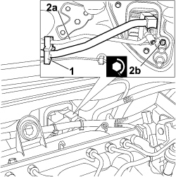
1. Secure the pipe to the retaining clip.
2. Connect pipe (2a), expansion valve side, and tighten nut (2b) to the recommended torque.
| Component | Fastening | dia | Value (daNm) | Validity |
|---|---|---|---|---|
| Supply/return pipes (on expansion valve) | Nut | M10x1.25 | 3.5 | all versions |
Op. 1056B15 THROTTLE BODY INTERGRAL WITH MDS - R.R.
Op. 0010T84 COOLANT FOR AIR CONDITIONING SYSTEM - DEHYDRATE AND REPRESSURIZE
- Connect the water return pipe from the heater, heater side and close the retaining band.
Op. 5010A12 HEATER WATER SUPPLY PIPE - R.R.
Op. 5530B52 BATTERY SUPPORT/DRIP TRAY - R.R
Op. 0010T21 ENGINE COOLANT - CHECK DENSITY AND TOP UP, IF NECESSARY
Op. 1048B44 RIGID AIR SUPPLY PIPE BETWEEN HEAT EXCHANGER AND INTAKE MANIFOLD - R.R.
Op. 1048A10 AIR FILTER ASSEMBLY - R.R.
Op. 1048A23 COLD AIR INTAKE FOR AIR FILTER - R.R
Op. 7040A10 DASHBOARD TRIM - R+R
- Refit both diffusers:
Op. 5010C26 FRONT SIDE PANEL AIR DIFFUSER, L.H. OR R.H. - R R
Op. 5010C12 WINDSCREEN DEMISTER DIFFUSER - R+R
Op. 5010C30 CENTRAL AIR VENT IN DASHBOARD - R.R.
Op. 5570T80 CAR RADIO EQUIPMENT - R+R
Op. 7040A44 LEFT DASHBOARD SIDE TRIM - R.R.
Op. 7040A49 CONNECTOR HOLDER TRIM FOR EOBD - R.R.
Op. 7040A41 SPEAKER GRILLE (ONE) LH OR RH ON INSTRUMENT FACIA - R R
Op. 7040A56 SWITCH UNIT IN DASHBOARD - R.R.
Op. 7040L20 TUNNEL COVER - R.R
- Refit both the electric window switches:
Op. 7005M10 ELECTRIC WINDOW CONTROL SWITCH (ONE) FOR ONE FRONT DOOR - R.R.
- Refit both centre console side trims:
Op. 7040A65 CONSOLE SIDE CLOSING (ONE) - R.R.
Op. 7040A28 TRIM ON GEARBOX CONTROL PANEL - R.R.
Op. 2125C02 GEAR CONTROL LEVER OUTER BOOT - R.R.
Op. 2125C24 GEAR LEVER KNOB - R + R
Op. 5520A14 IGNITION KEY LOCK BARREL - R+R
Op. 5560B10 CONTROL PANEL - R+R
Op. 7040A23 INSTRUMENT PANEL FRAME IN DASHBOARD - R.R
Op. 5550A10 STALK UNIT ASSEMBLY - R+R
Op. 4110A10 STEERING WHEEL - R+R FOR REPLACEMENT OR CHECKS
Op. 5580C18 AIR BAG MODULE - R+R
Op. 5580E08 AERIAL FOR ELECTRONIC KEY (CODE) - R.R
Op. 7040A26 STEERING COLUMN TRIM - R+R
- For vehicles with knee Air Bag carry out the following operation:
Op. 5580C23 DRIVER'S KNEE BAG - R.R.
- For vehicles without knee Air Bag carry out the following operation:
Op. 7040A30
- Refit both the front doors:
Op. 7210E36 R.R. FRONT SIDE DOOR
- Refit both running board connectors:
Op. 7040L42
- Connect the negative battery terminal.
| Description | Connector | |
|---|---|---|
| Battery | See A001 BATTERY |
Removing
Before working on the Air Bag system, follow the safety instructions for working on the system very carefully.
- Disconnect the negative battery terminal.
| Description | Connector | |
|---|---|---|
| Battery | See A001 BATTERY |
- Remove both running board connectors
Op. 7040L42
- Remove both the front doors:
Op. 7210E36 R.R. FRONT SIDE DOOR
- For vehicles with knee bags, carry out the following operation:
Op. 5580C23 DRIVER'S KNEE BAG - R.R.
- For vehicles without knee bags, carry out the following operation:
Op. 7040A30
- Carry out the following operations on all vehicles:
Op. 7040A26 STEERING COLUMN TRIM - R+R
Op. 5580E08 AERIAL FOR ELECTRONIC KEY (CODE) - R.R
Op. 5580C18 AIR BAG MODULE - R+R
Op. 4110A10 STEERING WHEEL - R+R FOR REPLACEMENT OR CHECKS
Op. 5550A10 STALK UNIT ASSEMBLY - R+R
Op. 7040A23 INSTRUMENT PANEL FRAME IN DASHBOARD - R.R
Op. 5560B10 CONTROL PANEL - R+R
Op. 5520A14 IGNITION KEY LOCK BARREL - R+R
Op. 2125C24 GEAR LEVER KNOB - R + R
Op. 2125C02 GEAR CONTROL LEVER OUTER BOOT - R.R.
Op. 7040A28 TRIM ON GEARBOX CONTROL PANEL - R.R.
- Remove both centre console side trims:
Op. 7040A65 CONSOLE SIDE CLOSING (ONE) - R.R.
- Remove both electric window switches:
Op. 7005M10 ELECTRIC WINDOW CONTROL SWITCH (ONE) FOR ONE FRONT DOOR - R.R.
Op. 7040L20 TUNNEL COVER - R.R
Op. 7040A56 SWITCH UNIT IN DASHBOARD - R.R.
Op. 7040A41 SPEAKER GRILLE (ONE) LH OR RH ON INSTRUMENT FACIA - R R
Op. 7040A49 CONNECTOR HOLDER TRIM FOR EOBD - R.R.
Op. 7040A44 LEFT DASHBOARD SIDE TRIM - R.R.
Op. 5570T80 CAR RADIO EQUIPMENT - R+R
Op. 5010C30 CENTRAL AIR VENT IN DASHBOARD - R.R.
Op. 5010C12 WINDSCREEN DEMISTER DIFFUSER - R+R
- Remove both vents:
Op. 5010C26 FRONT SIDE PANEL AIR DIFFUSER, L.H. OR R.H. - R R
Op. 7040A10 DASHBOARD TRIM - R+R
- Remove both the pillar trims:
Op. 7040H30 FRONT PILLAR TRIM (ONE), LEFT OR RIGHT - R.R.
Op. 1048A23 COLD AIR INTAKE FOR AIR FILTER - R.R
Op. 1048A10 AIR FILTER ASSEMBLY - R.R.
Op. 0010T20 ENGINE COOLANT - CHANGE
Op. 1056B82 INJECTION/IGNITION SYSTEM E.C.U. (ONE) - R + R
Op. 5530B52 BATTERY SUPPORT/DRIP TRAY - R.R
Op. 5010A12 HEATER WATER SUPPLY PIPE - R.R.
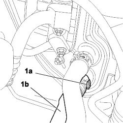
- Position a suitable container for collecting the refrigerant fluid.
1. Open the retaining band (1a) and disconnect the water return pipe (1b), heater side.
Op. 0010T84 COOLANT FOR AIR CONDITIONING SYSTEM - DEHYDRATE AND REPRESSURIZE
Op. 1056B15 THROTTLE BODY INTERGRAL WITH MDS - R.R.
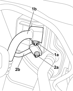
2. Undo the fixing nut (2a) and disconnect the high pressure pipe (2b), expansion valve side.
1. Undo the nut (1a) securing the pipe (1b), expansion valve side.
Seal the connectors that have been disconnected using suitable plugs to prevent dampness and impurities from entering the system.
Op. 4110D20 STEERING ELECTRICAL CONTROL DEVICE - R R
Op. 5010C55 RIGHT LOWER AIR DIFFUSER - R+R
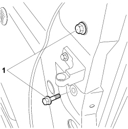
1. Undo the bolts securing the crossmember on both sides.
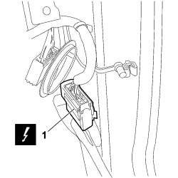
1. Detach the electrical connection.
| Description | Connector | |
|---|---|---|
| 1 | Dashboard/rear coupling | See D020 DASHBOARD/REAR COUPLING |
- Disconnect the aerial.
| Description | Connector | |
|---|---|---|
| Coaxial cable for radio aerial coupling | See D168 COAXIAL CABLE FOR RADIO AERIAL COUPLING |
1. Detach the electrical connection.
| Description | Connector | |
|---|---|---|
| 1 | Dashboard bridge coupling | See D259 INSTRUMENT PANEL BRIDGE COUPLING |
2. Disconnect the electrical connection for the Air Bag control unit.
| Description | Connector | |
|---|---|---|
| 2 | Air Bag control unit | See M060 AIR BAG CONTROL UNIT |
3. Undo the fixing nut (3a) and disconnect the earth connection (3b).
| Description | Connector | |
|---|---|---|
| 3b | Air Bag system earth | See C050 AIR BAG SYSTEM EARTH |
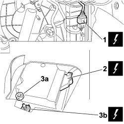
1. Detach the electrical connection.
| Description | Connector | |
|---|---|---|
| 1 | Front/dashboard coupling | See D001 FRONT/DASHBOARD COUPLING |
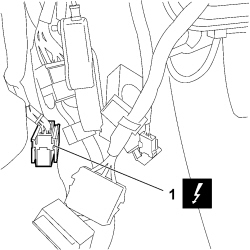
1. Undo the fixing nut (1a) and disconnect the earth connection (1b).
| Description | Connector | |
|---|---|---|
| 1b | Driver''s dashboard earth | See C015 DASHBOARD EARTH, DRIVER'S SIDE |
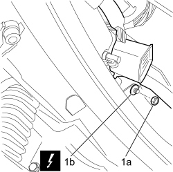
1. Disconnect the electrical connections for the Body Computer.
| Description | Connector | |
|---|---|---|
| 1 | Body computer | See M001 BODY COMPUTER |
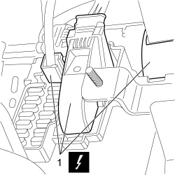
1. Undo the nuts (1a) and the bolt (1b) fixing the gear lever support.
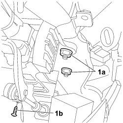
1. Undo the bolts fixing the gear lever mounting bracket.
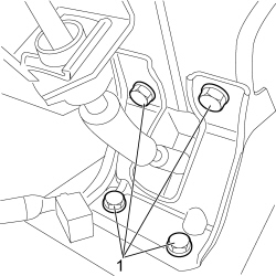
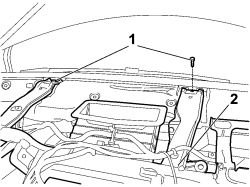
1. Undo the fixing bolts at the base of the windscreen.
2. Remove the crossmember complete with climate control unit.
Refitting
- Place the crossmember complete with climate control unit in position.
- Tighten the fixing bolts at the base of the windscreen.
- Tighten the bolts fixing the gear lever mounting bracket.
- Tighten the bolt fixing the gear lever support.
- Tighten the nuts fixing the gear lever support.
1. Connect the electrical connections for the Body Computer.
| Description | Connector | |
|---|---|---|
| 1 | Body computer | See M001 BODY COMPUTER |
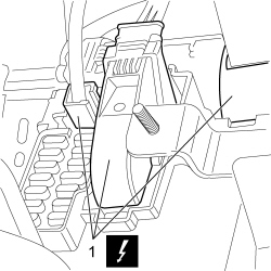
1. Secure the electrical connection.
| Description | Connector | |
|---|---|---|
| 1 | Front/dashboard coupling | See D001 FRONT/DASHBOARD COUPLING |
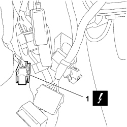
1. Connect the earth connection (1a) and tighten the fixing nut (1b).
| Description | Connector | |
|---|---|---|
| 1 | Driver''s dashboard earth | See C015 DASHBOARD EARTH, DRIVER'S SIDE |
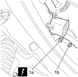
1. Secure the electrical connection.
| Description | Connector | |
|---|---|---|
| 1 | Dashboard bridge coupling | See D259 INSTRUMENT PANEL BRIDGE COUPLING |
2. Connect the electrical connection for the Air Bag control unit.
| Description | Connector | |
|---|---|---|
| 2 | Air Bag control unit | See M060 AIR BAG CONTROL UNIT |
3. Connect the earth connection (3a) and tighten the fixing nut (3b).
| Description | Connector | |
|---|---|---|
| 3a | Air Bag system earth | See C050 AIR BAG SYSTEM EARTH |
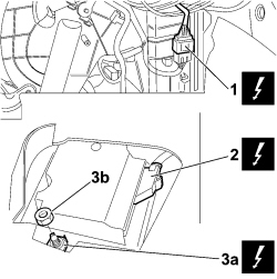
1. Secure the electrical connection.
| Description | Connector | |
|---|---|---|
| 1 | Dashboard/rear coupling | See D020 DASHBOARD/REAR COUPLING |
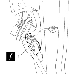
- Connect the aerial.
| Description | Connector | |
|---|---|---|
| Coaxial cable for radio aerial coupling | See D168 COAXIAL CABLE FOR RADIO AERIAL COUPLING |
1. Tighten the bolts securing the crossmember on both sides to the recommended torque.
| Component | Fastening | dia | Value (daNm) | Validity |
|---|---|---|---|---|
| Instrument panel (on side panels) | Bolt | M8 | 2.0 | all versions |
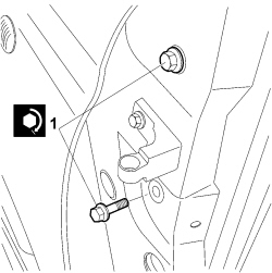
Op. 5010C55 RIGHT LOWER AIR DIFFUSER - R+R
Op. 4110D20 STEERING ELECTRICAL CONTROL DEVICE - R R
- Remove the protective plugs from the air conditioning refrigerant rigid pipes.
- Replace the o-rings for the air conditioning refrigerant fluid rigid pipe connectors using seals resistant to R134A refrigerant fluid.
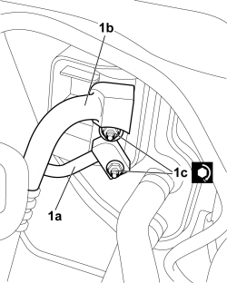
1. Connect the high pressure (1a) and low pressure (1b) pipes, expansion valve side and tighten the fixing nuts (1c) to the recommended torque.
| Component | Fastening | dia | Value (daNm) | Validity |
|---|---|---|---|---|
| Supply/return pipes (on expansion valve) | Nut | M10x1.25 | 3.5 | all versions |
Op. 0010T84 COOLANT FOR AIR CONDITIONING SYSTEM - DEHYDRATE AND REPRESSURIZE
Op. 1056B15 THROTTLE BODY INTERGRAL WITH MDS - R.R.
- Connect the heater water return pipe, heater side and close the retaining band.
Op. 5010A12 HEATER WATER SUPPLY PIPE - R.R.
Op. 5530B52 BATTERY SUPPORT/DRIP TRAY - R.R
Op. 1056B82 INJECTION/IGNITION SYSTEM E.C.U. (ONE) - R + R
Op. 0010T20 ENGINE COOLANT - CHANGE
Op. 1048A10 AIR FILTER ASSEMBLY - R.R.
Op. 1048A23 COLD AIR INTAKE FOR AIR FILTER - R.R
- Refit both the pillar trims:
Op. 7040H30 FRONT PILLAR TRIM (ONE), LEFT OR RIGHT - R.R.
Op. 7040A10 DASHBOARD TRIM - R+R
- Refit both vents:
Op. 5010C26 FRONT SIDE PANEL AIR DIFFUSER, L.H. OR R.H. - R R
Op. 5010C12 WINDSCREEN DEMISTER DIFFUSER - R+R
Op. 5010C30 CENTRAL AIR VENT IN DASHBOARD - R.R.
Op. 5570T80 CAR RADIO EQUIPMENT - R+R
Op. 7040A44 LEFT DASHBOARD SIDE TRIM - R.R.
Op. 7040A49 CONNECTOR HOLDER TRIM FOR EOBD - R.R.
Op. 7040A41 SPEAKER GRILLE (ONE) LH OR RH ON INSTRUMENT FACIA - R R
Op. 7040A56 SWITCH UNIT IN DASHBOARD - R.R.
Op. 7040L20 TUNNEL COVER - R.R
- Refit both electric window switches:
Op. 7005M10 ELECTRIC WINDOW CONTROL SWITCH (ONE) FOR ONE FRONT DOOR - R.R.
- Refit both centre console side trims:
Op. 7040A65 CONSOLE SIDE CLOSING (ONE) - R.R.
Op. 7040A28 TRIM ON GEARBOX CONTROL PANEL - R.R.
Op. 2125C02 GEAR CONTROL LEVER OUTER BOOT - R.R.
Op. 2125C24 GEAR LEVER KNOB - R + R
Op. 5520A14 IGNITION KEY LOCK BARREL - R+R
Op. 5560B10 CONTROL PANEL - R+R
Op. 7040A23 INSTRUMENT PANEL FRAME IN DASHBOARD - R.R
Op. 5550A10 STALK UNIT ASSEMBLY - R+R
Op. 4110A10 STEERING WHEEL - R+R FOR REPLACEMENT OR CHECKS
Op. 5580C18 AIR BAG MODULE - R+R
Op. 5580E08 AERIAL FOR ELECTRONIC KEY (CODE) - R.R
Op. 7040A26 STEERING COLUMN TRIM - R+R
- For vehicles with knee bags, carry out the following operation:
Op. 5580C23 DRIVER'S KNEE BAG - R.R.
- For vehicles without knee bags, carry out the following operation:
Op. 7040A30
- Refit both the front doors:
Op. 7210E36 R.R. FRONT SIDE DOOR
- Refit both running board connectors:
Op. 7040L42
Op. 0010T21 ENGINE COOLANT - CHECK DENSITY AND TOP UP, IF NECESSARY
- Connect the negative battery terminal.
| Description | Connector | |
|---|---|---|
| Battery | See A001 BATTERY |
Parts & tools for this job For 2007 Fiat 500
- TOOLTrim removal tool kitSearch: trim removal tool kit
- PARTTouch-up paintSearch: Fiat touch up paint
- PARTPanel clip assortmentSearch: Fiat panel clips assortment
Links open Amazon search results in a new tab. As an Amazon Associate I earn from qualifying purchases.