
Front end assembly - r.r.
- Make
- Fiat
- Model
- 500 Factory Service Manual
- Year
- 2007–2024
- Section
- Removing-refitting › Front end assembly - r.r.
FRONT END ASSEMBLY - R.R.
Removing
Op. 0010T84 COOLANT FOR AIR CONDITIONING SYSTEM - DEHYDRATE AND REPRESSURIZE
- Position the vehicle on a lift.
- Disconnect the negative battery terminal.
| Description | Connector | |
|---|---|---|
| Battery | See A001 BATTERY |
- Position a suitable container for collecting the engine coolant.
Op. 0010T20 ENGINE COOLANT - CHANGE
Op. 4450B12 FRONT WHEELS (TWO) - R+R
Op. 4410D22 BRACKET FIXING FRONT SUSPENSION CROSSMEMBER TO BODYSHELL (ONE), LEFT OR RIGHT - R.R.
Op. 7055B66 ENGINE COMPARTMENT DUST COVER IN RIGHT FRONT WHEEL ARCH - R.R.
Op. 5540B70 LEFT FRONT LIGHT CLUSTER WITH DIRECTION INDICATOR - R.R.
Op. 5540B71 RIGHT FRONT LIGHT CLUSTER WITH DIRECTION INDICATOR - R.R.
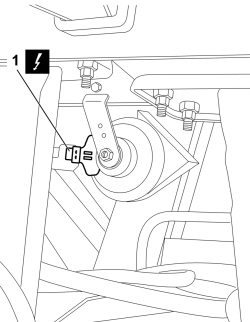
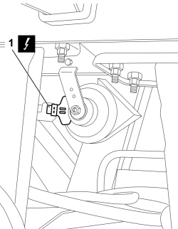
1. Disconnect the electrical connection for the horn.
| Description | Connector | |
|---|---|---|
| 1 | Single tone horn | See P005 SINGLE-TONE HORN |
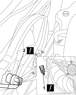
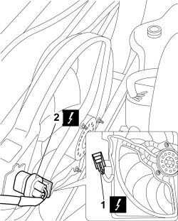
1. Disconnect the electrical connection for the engine cooling fan.
| Description | Connector | |
|---|---|---|
| 1 | Engine fan motor | See N011 FAN MOTOR |
2. Disconnect the electrical connection for the engine fan adjustment heater coil.
| Description | Connector | |
|---|---|---|
| 2 | Engine fan adjustment heater coil | See O010 ENGINE FAN ADJUSTMENT RESISTANCE - 1 |
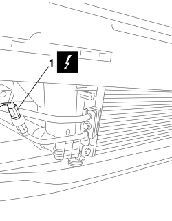
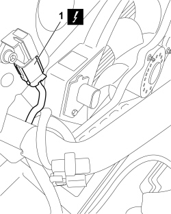
1. Disconnect the electrical connection for the linear sensor.
| Description | Connector | |
|---|---|---|
| 1 | Linear sensor (for climate control) | See K120 LINEAR SENSOR FOR FANS |
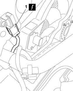
1. Disconnect the electrical connection for the front end impact sensor.
| Description | Connector | |
|---|---|---|
| 1 | Air Bag front sensor | See K039 FRONT AIR BAG SENSOR |
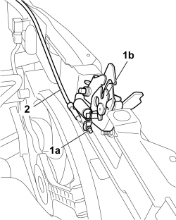
1. Disconnect idler link (1a) from bonnet catch (1b).
2. Release the bonnet opening cable from the retaining clip on the front-end.
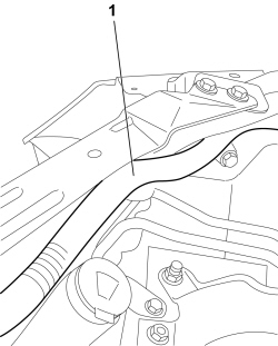
1. Release the section of the front wiring wiring looms from the retaining clips on the front-end.
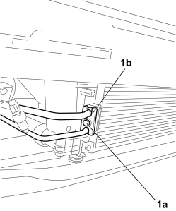
1. Unscrew bolt (1a) and disconnect bracket (1b) complete with high and low pressure air conditioning system pipes from the condenser.
- Open the retaining bands and disconnect the engine coolant inlet and outlet pipes, radiator side.
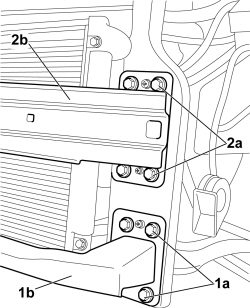
1. Undo all bolts (1a) securing lower front sacrificial beam (1b).
- Carry out the same operation for the remaining side.
The bolts secure the lower front sacrificial beam to the third load line.
2. Undo all bolts (2a) securing upper front sacrificial beam (2b).
- Carry out the same operation for the remaining side.
The bolts secure the upper front sacrificial beam to the strut.
1. Undo the bolts on the front-end body.
- Carry out the same operation for the remaining side.
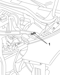
- Remove the front-end with the help of a second mechanic.
- Place the front-end on a suitable footboard.
Refitting
1. Position the front-end in its housing and tighten the upper bolts on the body to torque.
| Component | Fastening | dia | Value (daNm) | Validity |
|---|---|---|---|---|
| Front end (upper fastenings on body) | Bolt | M8 | 2.4 | all versions |
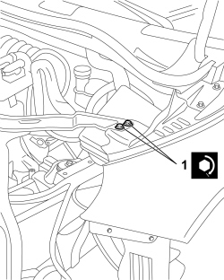
1. Tighten retaining bolts (1a) on the front, lower (1b) and upper (1c) sacrificial beam to torque.
| Component | Fastening | dia | Value (daNm) | Validity |
|---|---|---|---|---|
| Front end (lower fastenings on body) | Bolt | M8 | 4.0 | all versions |
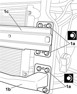
- Connect the engine coolant inlet and outlet pipes, radiator side, and secure with the retaining clips.
- Connect the high and low pressure pipes complete with retaining bracket from the air conidtioning system to the condenser.
1. Tighten retaining bolt (1a) for retaining bracket (1b) for the air conditioning system high and low pressure pipes on the condensor.
| Component | Fastening | dia | Value (daNm) | Validity |
|---|---|---|---|---|
| Supply/return pipes (on condenser) | Bolt | M8 | 2.0 | all versions |
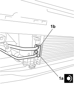
- Attach the section of the front wiring wiring looms from the retaining clips on the front-end.
- Connect the idler link to the bonnet catch.
- Attach the bonnet opening cable to the retaining clip on the front-end.
1. Connect the electrical connection for the front end impact sensor.
| Description | Connector | |
|---|---|---|
| 1 | Air Bag front sensor | See K039 FRONT AIR BAG SENSOR |
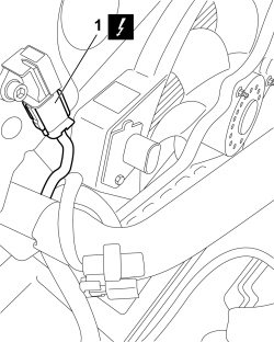
1. Connect the electrical connection for the linear sensor.
| Description | Connector | |
|---|---|---|
| Linear sensor (for climate control) | See K120 LINEAR SENSOR FOR FANS |
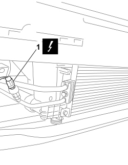
1. Connect the electrical connection for the engine cooling fan.
| Description | Connector | |
|---|---|---|
| Engine fan motor | See N011 FAN MOTOR |
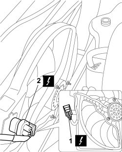
2. Connect the electrical connection for the engine fan adjustment heater coil.
| Description | Connector | |
|---|---|---|
| Engine fan adjustment heater coil | See O010 ENGINE FAN ADJUSTMENT RESISTANCE - 1 |
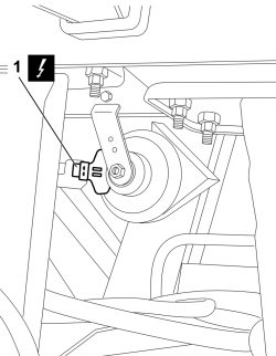
1. Connect the electrical connection for the horn.
| Description | Connector | |
|---|---|---|
| Single tone horn | See P005 SINGLE-TONE HORN |
Op. 5540B71 RIGHT FRONT LIGHT CLUSTER WITH DIRECTION INDICATOR - R.R.
Op. 5540B70 LEFT FRONT LIGHT CLUSTER WITH DIRECTION INDICATOR - R.R.
Op. 7055B66 ENGINE COMPARTMENT DUST COVER IN RIGHT FRONT WHEEL ARCH - R.R.
Op. 4410D22 BRACKET FIXING FRONT SUSPENSION CROSSMEMBER TO BODYSHELL (ONE), LEFT OR RIGHT - R.R.
Op. 4450B12 FRONT WHEELS (TWO) - R+R
- Connect the negative battery terminal.
| Description | Connector | |
|---|---|---|
| Battery | See A001 BATTERY |
- Remove the vehicle from the lift.
Op. 0010T84 COOLANT FOR AIR CONDITIONING SYSTEM - DEHYDRATE AND REPRESSURIZE
Op. 0010T20 ENGINE COOLANT - CHANGE
Removing
- Position the vehicle on a lift.
- Disconnect the negative battery terminal.
| Description | Connector | |
|---|---|---|
| Battery | See A001 BATTERY |
- Position a suitable container for collecting the coolant.
Op. 0010T20 ENGINE COOLANT - CHANGE
Op. 4450B12 FRONT WHEELS (TWO) - R+R
Op. 4410D22 BRACKET FIXING FRONT SUSPENSION CROSSMEMBER TO BODYSHELL (ONE), LEFT OR RIGHT - R.R.
Op. 7055B66 ENGINE COMPARTMENT DUST COVER IN RIGHT FRONT WHEEL ARCH - R.R.
Op. 5540B70 LEFT FRONT LIGHT CLUSTER WITH DIRECTION INDICATOR - R.R.
Op. 5540B71 RIGHT FRONT LIGHT CLUSTER WITH DIRECTION INDICATOR - R.R.
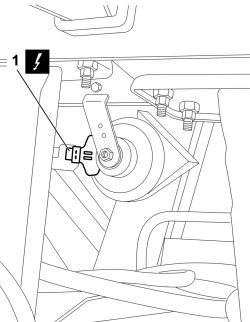
1. Disconnect the electrical connection for the horn.
| Description | Connector | |
|---|---|---|
| 1 | Single tone horn | See P005 SINGLE-TONE HORN |
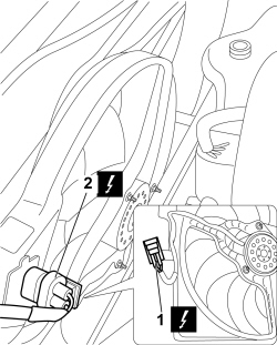
1. Disconnect the electrical connection for the engine cooling fan.
| Description | Connector | |
|---|---|---|
| 1 | Engine fan motor | See N011 FAN MOTOR |
2. Disconnect the electrical connection for the engine fan regulation resistance.
| Description | Connector | |
|---|---|---|
| 2 | Engine fan adjustment resistance | See O010 ENGINE FAN ADJUSTMENT RESISTANCE - 1 |
1. Disconnect the electrical connection for the linear sensor.
| Description | Connector | |
|---|---|---|
| 1 | Linear sensor (for climate control) | See K120 LINEAR SENSOR FOR FANS |
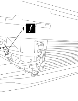
1. Disconnect the electric connection for the front impact sensor.
| Description | Connector | |
|---|---|---|
| 1 | Air Bag front sensor | See K039 FRONT AIR BAG SENSOR |
1. Disconnect the idler rod (1a) from the bonnet lock (1b).
2. Release the bonnet opening cable from the retaining clips on the front end.
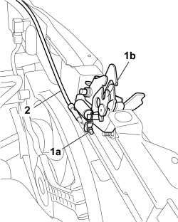
1. Release the front wiring cable loom from the retaining clips on the front end.
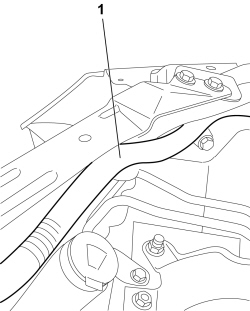
1. Open the band (1a) and disconnect the air supply pipe between the turbocharger and the heat exchanger (1b).
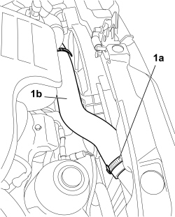
1. Open the bands (1a) and disconnect the air supply hose between the heat exchanger and the rigid pipe (1b).
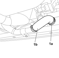
1. Unscrew the bolt (1a) and disconnect high and low pressure pipes (1b), condenser side, complete with mounting bracket.
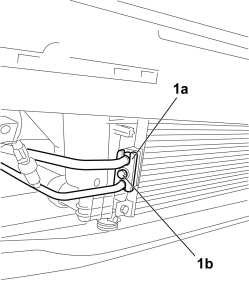
- Open the retaining bands and disconnect the engine coolant inlet and outlet pipes, radiator side.
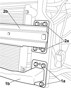
1. Undo all the bolts (1a) fixing the lower front crossmember (1b).
- Carry out the same operation for the remaining side.
The bolts secure the lower front crossmember to the third load line.
2. Undo all the bolts (2a) fixing the upper front crossmember (2b).
- Carry out the same operation for the remaining side.
The bolts secure the upper front crossmember to the strut.
1. Undo the bolts securing the front-end to the body.
- Carry out the same operation for the remaining side.
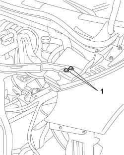
- Remove the front end with the help of a second mechanic.
- Rest the front end on a suitable support.
Refitting
1. Place the front end in position and tighten the upper fixing bolts on the body to torque.
| Component | Fastening | dia | Value (daNm) | Validity |
|---|---|---|---|---|
| Front end (upper fastenings on body) | Bolt | M8 | 2.4 | all versions |
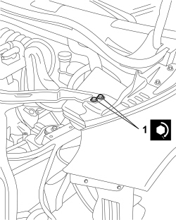
1. Tighten the bolts (1a) fixing the front, lower (1b) and upper (1c) crossmembers to torque.
| Component | Fastening | dia | Value (daNm) | Validity |
|---|---|---|---|---|
| Front end (lower fastenings on body) | Bolt | M8 | 4.0 | all versions |
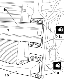
- Connect the engine coolant inlet and outlet pipes, radiator side and secure them using the retaining bands.
- Connect the air conditioning system low and high pressure pipes to the condenser, complete with retaining bracket.
1. Tighten the bolt (1a) fixing the high and low pressure pipes retaining bracket (1b), condenser side to torque.
| Component | Fastening | dia | Value (daNm) | Validity |
|---|---|---|---|---|
| Supply/return pipes (on condenser) | Bolt | M8 | 2.0 | all versions |
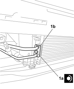
- Connect the air supply hose from the heat exchanger to the rigid pipe and secure it to the retaining band.
- Connect the intermediate air supply pipe between the turbocharger and the heat exchanger and secure it to the retaining band.
- Secure the front wiring cable loom from the retaining clips on the front end.
- Connect the idler rod to the bonnet lock.
- Secure the bonnet opening cable to the retaining clips on the front end.
1. Connect the electric connection for the front impact sensor.
| Description | Connector | |
|---|---|---|
| 1 | Air Bag front sensor | See K039 FRONT AIR BAG SENSOR |
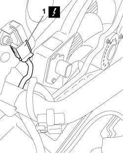
1. Connect the electrical connection for the linear sensor.
| Description | Connector | |
|---|---|---|
| Linear sensor (for climate control) | See K120 LINEAR SENSOR FOR FANS |
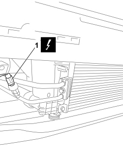
1. Connect the electrical connection for the engine cooling fan.
| Description | Connector | |
|---|---|---|
| Engine fan motor | See N011 FAN MOTOR |
2. Connect the electrical connection for the engine fan regulation resistance.
| Description | Connector | |
|---|---|---|
| Engine fan adjustment resistance | See O010 ENGINE FAN ADJUSTMENT RESISTANCE - 1 |
1. Connect the electrical connection for the horn.
| Description | Connector | |
|---|---|---|
| 1 | Single tone horn | See P005 SINGLE-TONE HORN |
Op. 5540B71 RIGHT FRONT LIGHT CLUSTER WITH DIRECTION INDICATOR - R.R.
Op. 5540B70 LEFT FRONT LIGHT CLUSTER WITH DIRECTION INDICATOR - R.R.
Op. 7055B66 ENGINE COMPARTMENT DUST COVER IN RIGHT FRONT WHEEL ARCH - R.R.
Op. 4410D22 BRACKET FIXING FRONT SUSPENSION CROSSMEMBER TO BODYSHELL (ONE), LEFT OR RIGHT - R.R.
Op. 4450B12 FRONT WHEELS (TWO) - R+R
- Connect the negative battery terminal.
| Description | Connector | |
|---|---|---|
| Battery | See A001 BATTERY |
- Remove the vehicle from the lift.
Op. 0010T84 COOLANT FOR AIR CONDITIONING SYSTEM - DEHYDRATE AND REPRESSURIZE
Parts & tools for this job For 2007 Fiat 500
- TOOLTrim removal tool kitSearch: trim removal tool kit
- PARTTouch-up paintSearch: Fiat touch up paint
- PARTPanel clip assortmentSearch: Fiat panel clips assortment
Links open Amazon search results in a new tab. As an Amazon Associate I earn from qualifying purchases.