
Stalk unit assembly - r+r
- Make
- Fiat
- Model
- 500 Factory Service Manual
- Year
- 2007–2024
- Section
- Warning and manoeuvring indicators › Stalk unit assembly - r+r
STALK UNIT ASSEMBLY - R+R
Removing
Before working on the Air Bag system, follow the safety instructions for working on the system very carefully
- Disconnect the negative battery terminal.
| Description | Connector | |
|---|---|---|
| Battery | See A001 BATTERY |
Op. 7040A26 STEERING COLUMN TRIM - R+R
Op. 5580C18 AIR BAG MODULE - R+R
Op. 4110A10 STEERING WHEEL - R+R FOR REPLACEMENT OR CHECKS
Be careful not to change the position of the clock spring; secure adequately the two shims until they cannot be accidentally moved.
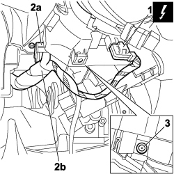
1. Disconnect the electric connector from the clock spring on the steering wheel interface assembly.
| Description | Connector | |
|---|---|---|
| 1 | Clock spring coupling | See D047 CLOCK SPRING COUPLING |
2. Undo retaining clip (2a) and release steering wheel interface wiring (2b).
3. Loosen the bolt and partially extract the steering wheel interface assembly.
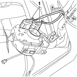
1. Disconnect the rear electrical connectors and remove the steering wheel interface assembly.
| Description | Connector | |
|---|---|---|
| 1 | Steering wheel interface | See H005 STEERING COLUMN SWITCH UNIT |
Refitting
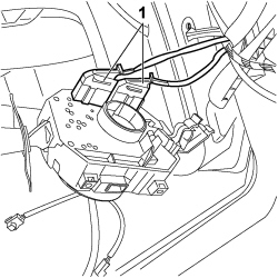
1. Connect the rear electrical connectors and place the steering wheel interface assembly in position.
| Description | Connector | |
|---|---|---|
| 1 | Steering wheel interface | See H005 STEERING COLUMN SWITCH UNIT |
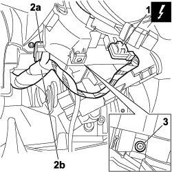
1. Connect the electric connector from the clock spring on the steering wheel interface assembly.
| Description | Connector | |
|---|---|---|
| 1 | Clock spring coupling | See D047 CLOCK SPRING COUPLING |
2. Secure retaining clip (2a) and steering wheel interface wiring (2b).
3. Tighten the bolt.
Op. 4110A10 STEERING WHEEL - R+R FOR REPLACEMENT OR CHECKS
Op. 5580C18 AIR BAG MODULE - R+R
Op. 7040A26 STEERING COLUMN TRIM - R+R
- Connect the negative battery terminal.
| Description | Connector | |
|---|---|---|
| Battery | See A001 BATTERY |
Parts & tools for this job For 2007 Fiat 500
- TOOLDigital multimeterSearch: automotive digital multimeter
- PARTAssorted fuse kitSearch: car fuse assortment kit
- TOOLWire crimper and connector kitSearch: wire crimper connector kit
Links open Amazon search results in a new tab. As an Amazon Associate I earn from qualifying purchases.