
Stalk unit
- Make
- Fiat
- Model
- 500 Factory Service Manual
- Year
- 2007–2024
- Section
- Warning and manoeuvring indicators › Stalk unit
STALK UNIT
INTRODUCTION
The diagram shows the steering wheel stalk unit.
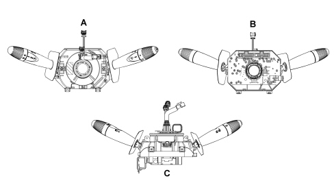
A. Front view
B. Rear view
C. Lower view
COMPONENTS AND OPERATION
The casing
The casing is the part of the steering column switch unit that contains the electrical circuits and the switching and automatic release mechanisms which return the left (direction) lever to the rest position, following the realignment of the steering wheel, after a manoeuvre has been carried out.
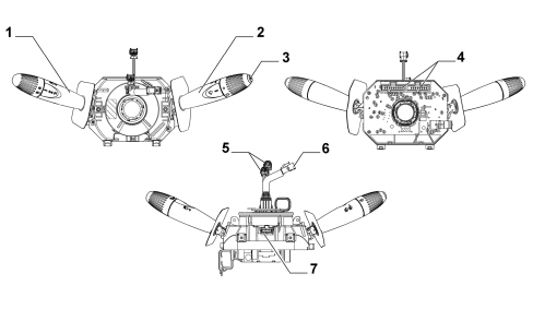
1. Left lever with lighting/direction controls
2. Right lever with front/rear wiper controls
3. Trip computer control button
4. Rear connectors
5. Electrical connections for Air Bag connection
6. Electrical connection for radio controls connection
7. Lower connector
The front section of the casing houses the clock spring which is the interface element with the steering wheel.
The rear part contains a collar with retaining strip for fastening it to the steering column and supplementary fastenings that establish the axial and angular position of the stalk unit on the steering column.
The steering wheel stalk unit case contains fastenings for the upper and lower cover halves.
The electronic module is connected to the casing.
The rear of the casing contains seats for the electrical connectors.
Electronic module
This is the electronic control unit which controls the wiper functions and it is mechanically fastened to the casing to which it is connected electrically by means of special terminals.
It controls the operation of the:
- Windscreen wiper: Sweep rate;
- Rearscreen wiper: Sweep rate and control during reversing;
- Windscreen wiper function: Smart washing;
- Rear washer function: Smart washing;
Clock spring
It has two functions:
- transmitting the rotation of the steering wheel to the automatic release mechanism located inside the casing;
- to transfer the electrical signal for the controls on the steering wheel (horn and other optional services) and the Air Bag module.
Multifunction switch or right lever
Includes lighting and turn signal controls.
All the controls are activated by operating either the stalk or the wheel control on the end of the stalk.
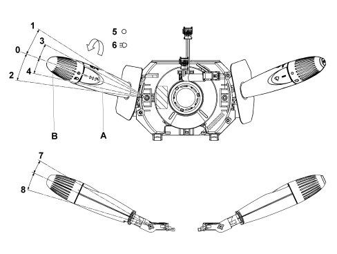
A. Lever
B. Main lighting switch (on ring nut)
0. DRL lights on (with ring nut in position 5) Dipped headlamps (with ring nut in position 6)
1. Right direction indicator (parking lights)
2. Left direction indicator (parking lights)
3. Right lane change (unstable)
4. Left lane change (unstable)
5. Light switch off
6. Main beam / dipped beam headlights enablement
7. Headlamp flasher
8. Main beam headlights (only with ring nut in position)
Main light switch
The control is located at the end of the lever is activated by turning the ring nut (end part of the lever).
The control is operated anticlockwise and offers 2 fixed positions:
- Pos. 5 = No circuit on (or DRL lights on if fitted)
- Pos. 6 = Side lights + low/high beam enablement + rear fog lamp.
All ring nut manoeuvres (from position 5 to 6 and viceversa) are only possible with the left lever in the dipped headlights position and these changes cannot be made with the lever in the main beam headlights position.
Dipped/main beam headlights switch
Activation is produced by moving the stalk perpendicular to the steering wheel (i.e. the lever pulled from the rest position towards the dashboard).
The control offers two positions, one UNSTABLE and one STABLE.
Lights may be switched between high/low beams only with the main lighting switch (B) in position 6.
Flasher control with main beam
This is operated by puling the stalk from rest position towards the steering wheel crown. The operation is UNSTABLE, i.e. the stalk returns to rest position when released.
Direction indicators control
This is operated by moving the stalk in the same plane as the steering wheel in both clockwise and anticlockwise directions.
The automatic release device is active in each STABLE position of the direction control and its function is to return the stalk to rest position once the steering wheel has been realigned.
Parking lights control
The side lights can be turned on with the key switched off (parking function) simply by turning the ring nut to position 6 (side lights all on and number plate lights on).
In this case, moving the lever along the steering wheel plane both clockwise and anti-clockwise beyond the position for the direction indicators control (positions 1 and 2) turns the side lights on on either right or left side depending on the selection made.
For more details see
See descriptions 5540 EXTERIOR LIGHTING
Multifunction switch or left lever
This includes the front and rear wiper controls. All the controls are activated by operating either the stalk or the wheel control on the actual lever. A button on the end of the stalk switch also controls trip computer functions.
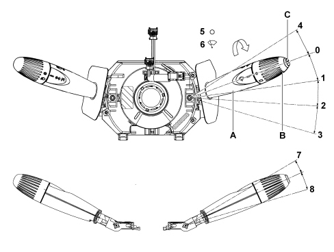
A. Lever
B. Rearscreen wiper control (on ring nut)
C. TRIP button
0. Off
1. Intermittent
2. 1st speed
3. 2nd speed
4. Antipanic (unstable)
5. Rearscreen wiper off
6. Rearscreen wiper continuous speed
7. Windscreen washer (unstable)
8. Rearscreen washer (unstable)
Windscreen wiper control
This is operated by moving the lever in the same plane as the steering wheel. The control can be operated to 5 different positions:
- Pos. 0 = No circuit activated (STABILE): POS. REST;
- Pos. 1 = Intermittent (STABLE): CLOCKWISE DIRECTION;
- Pos. 2 = Continuous 1st SPEED (STABLE): CLOCKWISE DIRECTION;
- Pos. 3 = Continuous 2nd SPEED (STABLE): CLOCKWISE DIRECTION;
- Pos. 4 = Antipanic function (UNSTABLE): ANTICLOCKWISE DIRECTION;
Windscreen washer control
This is operated by puling the stalk from rest position towards the steering wheel crown. The operation is UNSTABLE, i.e. the stalk returns to rest position when released.
The control simultaneously operates the windscreen wiper in smart washing mode (windscreen washer function).
Rearscreen wiper control
The control is located at the end of the lever and is operated by turning a wheel control.
The control offers 2 STABLE positions and is moved clockwise:
- Pos. 5 = No circuit operated;
- Pos. 6 = Rear wiper operated;
The following activate the rearscreen wiper:
- Specific rearscreen wiper command from the steering column switch unit;
- Engagement of reverse with windscreen wiper activated.
Rearscreen washer control
This is operated by pushing the stalk towards the facia. The operation is UNSTABLE, i.e. the stalk returns to rest position when released.
The control simultaneously operates the rear wiper in smart washing mode (windscreen washer function).
Electronic module (built into steering wheel stalk unit)
This is the electronic control unit that controls the operation of the electric motors, the windscreen wipers and the rearscreen wiper and the washing functions and it is mechanically fastened to the casing to which it is electrically connected by means of dedicated terminals.
In particular, it controls the operation of:
- Winscreen wiper (Sweep rate for all specifications);
- Rear wiper (Sweep rate and control during reversing);
- Screen washer function (Smart washing on all specifications);
- Rear washer function (Smart washing on all specifications)
Steering column switch unit electronic module pin out
The connectors in the steering column switch unit module are illustrated in the diagram below
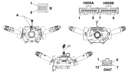
| Connector H005A pin out | |
|---|---|
| Pin | Function |
| 1 | Negative signal from trip computer button |
| 2 | Intermittent rearscreen wiper negative signal to NBC |
| 3 | N.C. |
| 4 | Rear windscreen washer pump control negative signal to NBC |
| 5 | N.C. |
| 6 | Windscreen washer pump/ headlamp washer control negative signal to NBC |
| 7 | Intermittent windscreen wiper negative signal to NBC |
| 8 | 1st speed windscreen wiper negative signal to NBC |
| 9 | 2nd speed windscreen wiper/antipanic negative signal to NBC |
| Connector H005B pin out | |
|---|---|
| Pin | Function |
| 1 | N.C. |
| 2 | Reference earth from NBC |
| 3 | Left direction indicators/parking lights control negative signal to NBC |
| 4 | Right direction indicators/parking lights control negative signal to NBC |
| 5 | Main beam headlamps flasher negative signal to NBC |
| 6 | Dipped headlights negative signal to NBC |
| 7 | Side lights control negative signal to NBC |
| 8 | N.C. |
| 9 | N.C. |
| Connector D047 pin out | |
|---|---|
| Pin | Function |
| 1 | preparation |
| 2 | preparation |
| 3 | Steering wheel controls input 1 (scan +/-, source, telephone) |
| 4 | Steering wheel controls input 2 (volume +/-, mute, voice) |
| 5 | Steering wheel controls lighting |
| 6 | Earth for analogue signals and steering wheel controls lighting earth |
| 7 | Horn earth |
| 8 | Horn |
| 9 | Driver''s Air Bag stage 2 + |
| 10 | Driver''s Air Bag stage 2 - |
| 11 | Driver''s Air Bag stage 1 + |
| 12 | Driver''s Air Bag stage 1 - |
| Connector A pinout | |
|---|---|
| Pin | Function |
| 1 | Driver''s Air Bag + |
| 2 | Driver''s Air Bag - |
| Connector B pin out | |
|---|---|
| Pin | Function |
| 1 | Steering wheel controls input 1 (scan +/-, source, telephone) |
| 2 | Steering wheel controls lighting |
| 3 | Horn earth |
| 4 | Horn |
| 5 | Steering wheel controls input 2 (volume +/-, mute, voice) |
| 6 | N.C. |
| 7 | Earth for analogue signals and steering wheel controls lighting earth |
| 8 | N.C. |
Parts & tools for this job For 2007 Fiat 500
- TOOLDigital multimeterSearch: automotive digital multimeter
- PARTAssorted fuse kitSearch: car fuse assortment kit
- TOOLWire crimper and connector kitSearch: wire crimper connector kit
Links open Amazon search results in a new tab. As an Amazon Associate I earn from qualifying purchases.