
Passenger compartment wiring - r.r
- Make
- Fiat
- Model
- 500 Factory Service Manual
- Year
- 2007–2024
- Section
- Instrument/gauge electrical circuits › Passenger compartment wiring - r.r
PASSENGER COMPARTMENT WIRING - R.R
Removing
- Position the vehicle on the lift.
The following preliminary operations must be carried out before removing and refitting the pretensioner for the front seat belt lumbar branch:
(1) turn the ignition key to the OFF position and extract it;
(2) disconnect the battery terminals and insulate them;
(3) wait for at least 10 minutes before continuing.
FOLLOW ALL THE RECOMMENDED SAFETY INSTRUCTIONS
Op. 0010T84 COOLANT FOR AIR CONDITIONING SYSTEM - DEHYDRATE AND REPRESSURIZE
- Have a suitable container for collecting the coolant ready.
Op. 0010T20 ENGINE COOLANT - CHANGE
Op. 1048A23 COLD AIR INTAKE FOR AIR FILTER - R.R
Op. 1048A10 AIR FILTER ASSEMBLY - R.R.
- THE OPERATIONS DESCRIBED BELOW ARE SPECIFIC TO THE 1.3 Multijet VERSIONS
Op. 1044B10 FUEL FILTER ASSEMBLY - R + R OR REPLACE
- THE OPERATIONS DESCRIBED BELOW ARE VALID FOR ALL ENGINE TYPES.
Op. 5530B52 BATTERY SUPPORT/DRIP TRAY - R.R
- THE OPERATIONS DESCRIBED BELOW ARE SPECIFIC TO THE 1.3 Multijet VERSIONS
Op. 1048B44 RIGID AIR SUPPLY PIPE BETWEEN HEAT EXCHANGER AND INTAKE MANIFOLD - R.R.
- THE OPERATIONS DESCRIBED BELOW ARE VALID FOR ALL ENGINE TYPES.
Op. 5010A12 HEATER WATER SUPPLY PIPE - R.R.
Op. 5050B34 WINDSCREEN WIPER ARM/S COMPLETE WITH BLADE - R+R
Op. 7210E22 R.R. WINDSCREEN BASE TRIM
Op. 5050B42 WINDSCREEN WIPER MOTOR - R+R
Op. 4450B12 FRONT WHEELS (TWO) - R+R
Op. 4410D22 BRACKET FIXING FRONT SUSPENSION CROSSMEMBER TO BODYSHELL (ONE), LEFT OR RIGHT - R.R.
Op. 7055B66 ENGINE COMPARTMENT DUST COVER IN RIGHT FRONT WHEEL ARCH - R.R.
- Remove both front pillar trims
Op. 7040H30 FRONT PILLAR TRIM (ONE), LEFT OR RIGHT - R.R.
- Remove both the sun blinds.
Op. 7065C34 SUN BLIND (ONE), LEFT OR RIGHT - R.R.
Op. 7040E10 FRONT COURTESY LIGHT - R+R
- Remove both centre pillar cover upper elements.
Op. 7040H38 CENTRE PILLAR UPPER ELEMENT (ONE), LEFT OR RIGHT - R.R
Op. 7040H20 ROOF TRIM SEAL (ONE) - REPLACE
Op. 7040H10 ROOF PANEL LINING - R.R.
- If the vehicle is equipped with knee bags
Op. 5580C23 DRIVER'S KNEE BAG - R.R.
Op. 7040A30
Op. 7040A26 STEERING COLUMN TRIM - R+R
Op. 5580E08 AERIAL FOR ELECTRONIC KEY (CODE) - R.R
Op. 5580C18 AIR BAG MODULE - R+R
Op. 4110A10 STEERING WHEEL - R+R FOR REPLACEMENT OR CHECKS
Op. 5550A10 STALK UNIT ASSEMBLY - R+R
Op. 7040A23 INSTRUMENT PANEL FRAME IN DASHBOARD - R.R
Op. 5560B10 CONTROL PANEL - R+R
Op. 2125C24 GEAR LEVER KNOB - R + R
Op. 2125C02 GEAR CONTROL LEVER OUTER BOOT - R.R.
Op. 7040A28 TRIM ON GEARBOX CONTROL PANEL - R.R.
- Remove both centre console side trims:
Op. 7040A65 CONSOLE SIDE CLOSING (ONE) - R.R.
- Remove both electric window switches:
Op. 7005M10 ELECTRIC WINDOW CONTROL SWITCH (ONE) FOR ONE FRONT DOOR - R.R.
Op. 7040A56 SWITCH UNIT IN DASHBOARD - R.R.
Op. 7040A41 SPEAKER GRILLE (ONE) LH OR RH ON INSTRUMENT FACIA - R R
Op. 7040A49 CONNECTOR HOLDER TRIM FOR EOBD - R.R.
Op. 7040A44 LEFT DASHBOARD SIDE TRIM - R.R.
Op. 5570T80 CAR RADIO EQUIPMENT - R+R
Op. 5010C30 CENTRAL AIR VENT IN DASHBOARD - R.R.
Op. 5010C12 WINDSCREEN DEMISTER DIFFUSER - R+R
- Remove both vents:
Op. 5010C26 FRONT SIDE PANEL AIR DIFFUSER, L.H. OR R.H. - R R
- Remove both the side doors:
Op. 7210E36 R.R. FRONT SIDE DOOR
Op. 7040A10 DASHBOARD TRIM - R+R
- Remove both front pillar trims:
Op. 7040H30 FRONT PILLAR TRIM (ONE), LEFT OR RIGHT - R.R.
Op. 4110D20 STEERING ELECTRICAL CONTROL DEVICE - R R
- Remove both lower air vents:
Op. 5010C55 RIGHT LOWER AIR DIFFUSER - R+R
Op. 7040A89 REINFORCEMENT BRACKET BETWEEN DASHBOARD SUPPORTING CROSSMEMER AND BODYSHELL - R.R.
Op. 7210A74 R R FACIA SUPPORT BEAM
Op. 7040H80 REAR PARCEL SHELF - R.R.
Op. 7050A19 REAR SEAT BACKREST - R.R
Op. 7050A20 ONE-PIECE REAR SEAT CUSHION - R.R.
Op. 7040H42 REAR PILLAR TRIM (ONE), LEFT OR RIGHT- R.R
Op. 7040G30 BOOT LIGHT BULB HOLDER - R.R.
Op. 7040H50 REAR PANEL (ONE), LEFT OR RIGHT - R.R
Op. 7065A13 PRETENSIONER FOR LUMBAR BRANCH OF ONE SEAT BELT, LEFT OR RIGHT - R.R.
Op. 7040L22 REAR COVER ON TUNNEL - R.R.
Op. 7040L20 TUNNEL COVER - R.R
Op. 7040L42
Op. 7040L40 FRONT DOOR RUNNING BOARD (ONE), LEFT OR RIGHT - R.R.
- Remove both the front seats:
Op. 7045A10 FRONT SEAT (ONE), LEFT OR RIGHT - R.R.
Op. 7040L10 PASSENGER COMPARTMENT FLOOR COVERING - R.R.
Op. 7015A04 TAILGATE INTERIOR PANEL - R+R
Op. 7040B22 LUGGAGE COMPARTMENT/LOAD PLATFORM MOULDING - R+R
Op. 7040B10 LOAD PLATFORM (LUGGAGE PLATFORM) TRIM - R+R
- Remove both luggage compartment side trims:
Op. 7040B06 SIDE TRIM (ONE) LEFT OR RIGHT, LOAD COMPARTMENT/LOAD PLATFORM - R.R.
Op. 5570T49 BLUETOOTH ELECTRONIC CONTROL UNIT - R.R.
- Remove both rear light clusters:
Op. 5540A44 REAR LIGHT CLUSTER (ONE), LEFT OR RIGHT - R.R.
Op. 5550D16 THIRD BRAKE LIGHT - R+R
- Remove both side repeaters:
Op. 5550C22 L/H OR R/H SIDE REPEATER (ONE) - R+R
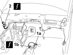
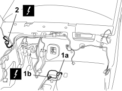
1. Disconnect the electrical connection (1a) and undo the earth point (1b) for the air bag control unit.
| Description | Connector | |
|---|---|---|
| 1a | AIR BAG CONTROL UNIT | See M060 AIR BAG CONTROL UNIT |
| Description | Connector | |
|---|---|---|
| 1b | AIR BAG SYSTEM EARTH | See C050 AIR BAG SYSTEM EARTH |
2. Disconnect the electrical connection for the engine compartment wiring coupling.
| Description | Connector | |
|---|---|---|
| 2 | FRONT/REAR COUPLING | See D006 FRONT/REAR COUPLING |
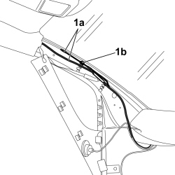
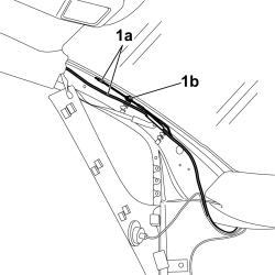
1. Release the aerial for the alarm and central locking receiver (1a) from the retainers on the front pillar (1b).
| Description | Connector | |
|---|---|---|
| 1a | AERIAL FOR CENTRAL LOCKING RECEIVER AND ALARM | See P093 AERIAL FOR ALARM AND CENTRAL LOCKING RECEIVER |
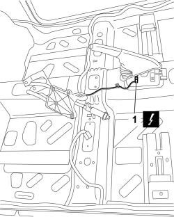
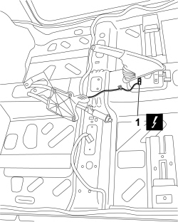
1. Disconnect the electrical connection for the handbrake switch.
| Description | Connector | |
|---|---|---|
| 1 | HANDBRAKE ON SWITCH | See I040 HANDBRAKE SWITCH |
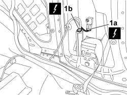
- Work on the driver''s side:
1. Disconnect the electrical connection for the driver''s side impact sensor (1a) and the connection for the pretensioner on the driver''s side reel (1b).
| Description | Connector | |
|---|---|---|
| 1a | SENSOR FOR DRIVER''S SIDE BAG | See K066 SENSOR FOR DRIVER'S SIDE BAG |
| Description | Connector | |
|---|---|---|
| 1b | DRIVER''S SIDE FRONT SEAT BELT PRETENSIONER | See Q020 DRIVER'S SEAT BELT PRETENSIONER |
- Proceed in the same way for the passenger side:
- Disconnect the electrical connection for the passenger side impact sensor and the connection for the pretensioner at the reel.
| Description | Connector | |
|---|---|---|
| SENSOR FOR PASSENGER SIDE BAG | See K067 SENSOR FOR PASSENGER SIDE BAG |
| Description | Connector | |
|---|---|---|
| PASSENGER FRONT SEAT BELT PRETENSIONER | See Q021 FRONT PASSENGER SEAT BELT PRETENSIONER |
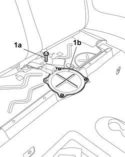
1. Undo the fixing bolts (1a) and remove the submerged pump cover (1b).
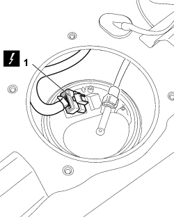
1. Disconnect the electrical connection for the submerged pump.
| Description | Connector | |
|---|---|---|
| 1 | FUEL PUMP AND LEVEL GAUGE | See N040 FUEL PUMP AND LEVEL GAUGE |
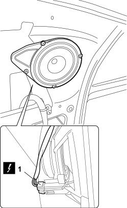
1. Disconnect the electrical connection for the left rear speaker.
| Description | Connector | |
|---|---|---|
| 1 | LEFT REAR SPEAKER | See P030 LEFT REAR SPEAKER |
- Work in the same way for the right speaker.
- Disconnect the electrical connection for the right rear speaker.
| Description | Connector | |
|---|---|---|
| RIGHT REAR SPEAKER | See P031 RIGHT REAR SPEAKER |
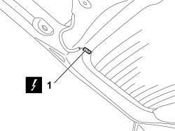
1. Disconnect heated rear windscreen electrical connections.
| Description | Connector | |
|---|---|---|
| 1 | HEATED REAR WINDSCREEN | See P055 HEATED REARSCREEN |
1. Disconnect the rear wiper motor electrical connection.
| Description | Connector | |
|---|---|---|
| 1 | REAR WIPER MOTOR | See N016 REAR WINDOW WIPER MOTOR |
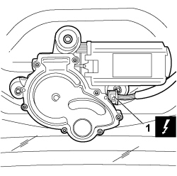
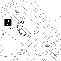
1. Disconnect the electrical connection for the number plate light assembly.
| Description | Connector | |
|---|---|---|
| 11 | NUMBER PLATE LIGHTS AND EXTERIOR BOOT OPENING SWITCH | See F055 No. plate lights and external boot opening switch |
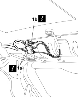
1. Disconnect the electrical connections for the GPS/GSM aerial (1a) and for the radio aerial (1b).
| Description | Connector | |
|---|---|---|
| 1a | GPS/GSM AERIAL | See P110 GPS/GSM AERIAL |
| Description | Connector | |
|---|---|---|
| 1b | AERIAL POWER SUPPLY/AMPLIFIER | See P025 AERIAL POWER SUPPLY |
1. Disconnect the electrical connection for the driver''s side window bag charging cylinder.
| Description | Connector | |
|---|---|---|
| 1 | DRIVER SIDE WINDOW BAG | See Q040 DRIVER'S HEAD BAG |
2. Undo the fixing nut and disconnect the earth point for the rearscreen.
| Description | Connector | |
|---|---|---|
| 2 | REAR WINDOW EARTH | See C032 REARSCREEN EARTH |
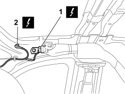
- Disconnect the electrical connection for the passenger side window bag charging cylinder.
| Description | Connector | |
|---|---|---|
| PASSENGER SIDE WINDOW BAG | See Q041 PASSENGER HEAD BAG |
1. Disconnect the electrical connection for the left rear wheel rpm sensor (1a) and release the cable duct seal (1b).
| Description | Connector | |
|---|---|---|
| 1a | LEFT REAR WHEEL SENSOR FOR ABS | See K075 LEFT REAR WHEEL SENSOR FOR ABS |
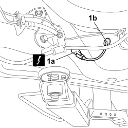
- Disconnect the electrical connection for the right rear wheel rpm sensor and release the cable duct seal.
| Description | Connector | |
|---|---|---|
| RIGHT REAR WHEEL SENSOR FOR ABS | See K076 RIGHT REAR WHEEL SENSOR FOR ABS. |
1. Disconnect the electrical connection for the parking sensor wiring.
| Description | Connector | |
|---|---|---|
| 1 | PARKING SENSOR CONTROL UNIT | See M084 PARKING SENSOR CONTROL UNIT |
2. Disconnect the electrical connections for the parking sensor control unit.
| Description | Connector | |
|---|---|---|
| 2 | PARKING SENSOR COUPLING | See D089 PARKING SENSOR COUPLING |
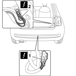
- Release the passenger compartment wiring from the retainers on the bodyshell and remove it.
Refitting
- Place the passenger compartment wiring in the vehicle and attach the retainers.
1. Connect the electrical connection to the parking sensor wiring.
| Description | Connector | |
|---|---|---|
| 1 | PARKING SENSOR CONTROL UNIT | See M084 PARKING SENSOR CONTROL UNIT |
2. Connect the electrical connections to the parking sensor control unit.
| Description | Connector | |
|---|---|---|
| 2 | PARKING SENSOR COUPLING | See D089 PARKING SENSOR COUPLING |
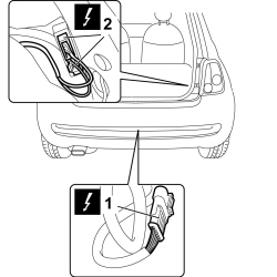
1. Connect the electrical connection for the left rear wheel rpm sensor (1a) and fit the cable duct seal (1b).
| Description | Connector | |
|---|---|---|
| 1a | LEFT REAR WHEEL SENSOR FOR ABS | See K075 LEFT REAR WHEEL SENSOR FOR ABS |
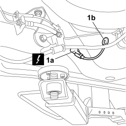
- Connect the electrical connection for the right rear wheel rpm sensor and fit the cable duct seal.
| Description | Connector | |
|---|---|---|
| RIGHT REAR WHEEL SENSOR FOR ABS | See K076 RIGHT REAR WHEEL SENSOR FOR ABS. |
1. Connect the electrical connection for the driver''s side window bag charging cylinder.
| Description | Connector | |
|---|---|---|
| 1 | DRIVER SIDE WINDOW BAG | See Q040 DRIVER'S HEAD BAG |
2. Connect the earth point for the rearscreen and tighten the fixing nut.
| Description | Connector | |
|---|---|---|
| 2 | REAR WINDOW EARTH | See C032 REARSCREEN EARTH |
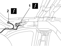
- Connect the electrical connection for the passenger side window bag charging cylinder.
| Description | Connector | |
|---|---|---|
| PASSENGER SIDE WINDOW BAG | See Q041 PASSENGER HEAD BAG |
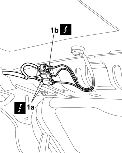
1. Connect the electrical connections for the GPS/GSM aerial (1a) and for the radio aerial (1b).
| Description | Connector | |
|---|---|---|
| 1a | GPS/GSM AERIAL | See P110 GPS/GSM AERIAL |
| Description | Connector | |
|---|---|---|
| 1b | AERIAL POWER SUPPLY/AMPLIFIER | See P025 AERIAL POWER SUPPLY |
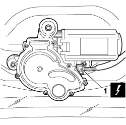
1. Connect the rear wiper motor electrical connection.
| Description | Connector | |
|---|---|---|
| 1 | REAR WIPER MOTOR | See N016 REAR WINDOW WIPER MOTOR |
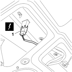
1. Connect the electrical connection for the number plate light assembly.
| Description | Connector | |
|---|---|---|
| 11 | NUMBER PLATE LIGHTS AND EXTERIOR BOOT OPENING SWITCH | See F055 No. plate lights and external boot opening switch |
1. Connect heated rear windscreen electrical connections.
| Description | Connector | |
|---|---|---|
| 1 | HEATED REAR WINDSCREEN | See P055 HEATED REARSCREEN |
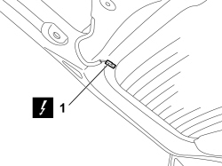
1. Connect the electrical connection for the left rear speaker.
| Description | Connector | |
|---|---|---|
| 1 | LEFT REAR SPEAKER | See P030 LEFT REAR SPEAKER |
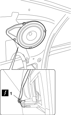
- Work in the same way for the right speaker.
- Connect the electrical connection for the right rear speaker.
| Description | Connector | |
|---|---|---|
| RIGHT REAR SPEAKER | See P031 RIGHT REAR SPEAKER |
1. Connect the electrical connection for the submerged pump.
| Description | Connector | |
|---|---|---|
| 1 | FUEL PUMP AND LEVEL GAUGE | See N040 FUEL PUMP AND LEVEL GAUGE |
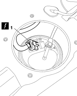
- Place the submerged pump cover in position and tighten the fixing bolts.
1. Connect the electrical connection for the driver''s side impact sensor (1a) and the connection for the pretensioner on the driver''s side reel (1b).
| Description | Connector | |
|---|---|---|
| 1a | SENSOR FOR DRIVER''S SIDE BAG | See K066 SENSOR FOR DRIVER'S SIDE BAG |
| Description | Connector | |
|---|---|---|
| 1b | DRIVER''S SIDE FRONT SEAT BELT PRETENSIONER | See Q020 DRIVER'S SEAT BELT PRETENSIONER |
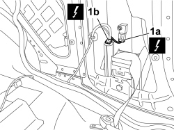
- Connect the electrical connection for the passenger side impact sensor and the connection for the pretensioner at the reel.
| Description | Connector | |
|---|---|---|
| SENSOR FOR PASSENGER SIDE BAG | See K067 SENSOR FOR PASSENGER SIDE BAG |
| Description | Connector | |
|---|---|---|
| PASSENGER FRONT SEAT BELT PRETENSIONER | See Q021 FRONT PASSENGER SEAT BELT PRETENSIONER |
1. Connect the electrical connection for the handbrake switch.
| Description | Connector | |
|---|---|---|
| 1 | HANDBRAKE ON SWITCH | See I040 HANDBRAKE SWITCH |
1. Attach the aerial for the alarm and central locking receiver (1a) to the retainers on the front pillar (1b).
| Description | Connector | |
|---|---|---|
| 1a | AERIAL FOR CENTRAL LOCKING RECEIVER AND ALARM | See P093 AERIAL FOR ALARM AND CENTRAL LOCKING RECEIVER |
1. Connect the electrical connection (1a) and undo the earth point (1b) for the air bag control unit.
| Description | Connector | |
|---|---|---|
| 1a | AIR BAG CONTROL UNIT | See M060 AIR BAG CONTROL UNIT |
| Description | Connector | |
|---|---|---|
| 1b | AIR BAG SYSTEM EARTH | See C050 AIR BAG SYSTEM EARTH |
2. Connect the electrical connection for the engine compartment wiring coupling.
| Description | Connector | |
|---|---|---|
| 2 | FRONT/REAR COUPLING | See D006 FRONT/REAR COUPLING |
- Fit both side repeaters:
Op. 5550C22 L/H OR R/H SIDE REPEATER (ONE) - R+R
Op. 5550D16 THIRD BRAKE LIGHT - R+R
- Fit both rear light clusters:
Op. 5540A44 REAR LIGHT CLUSTER (ONE), LEFT OR RIGHT - R.R.
Op. 5570T49 BLUETOOTH ELECTRONIC CONTROL UNIT - R.R.
- Fit both luggage compartment side trims:
Op. 7040B06 SIDE TRIM (ONE) LEFT OR RIGHT, LOAD COMPARTMENT/LOAD PLATFORM - R.R.
Op. 7040B10 LOAD PLATFORM (LUGGAGE PLATFORM) TRIM - R+R
Op. 7040B22 LUGGAGE COMPARTMENT/LOAD PLATFORM MOULDING - R+R
Op. 7015A04 TAILGATE INTERIOR PANEL - R+R
Op. 7040L10 PASSENGER COMPARTMENT FLOOR COVERING - R.R.
- Fit both the front seats:
Op. 7045A10 FRONT SEAT (ONE), LEFT OR RIGHT - R.R.
Op. 7040L40 FRONT DOOR RUNNING BOARD (ONE), LEFT OR RIGHT - R.R.
Op. 7040L42
Op. 7040L20 TUNNEL COVER - R.R
Op. 7040L22 REAR COVER ON TUNNEL - R.R.
Op. 7065A13 PRETENSIONER FOR LUMBAR BRANCH OF ONE SEAT BELT, LEFT OR RIGHT - R.R.
Op. 7040H50 REAR PANEL (ONE), LEFT OR RIGHT - R.R
Op. 7040G30 BOOT LIGHT BULB HOLDER - R.R.
Op. 7040H42 REAR PILLAR TRIM (ONE), LEFT OR RIGHT- R.R
Op. 7050A20 ONE-PIECE REAR SEAT CUSHION - R.R.
Op. 7050A19 REAR SEAT BACKREST - R.R
Op. 7040H80 REAR PARCEL SHELF - R.R.
Op. 7210A74 R R FACIA SUPPORT BEAM
Op. 7040A89 REINFORCEMENT BRACKET BETWEEN DASHBOARD SUPPORTING CROSSMEMER AND BODYSHELL - R.R.
- Fit both lower air vents:
Op. 5010C55 RIGHT LOWER AIR DIFFUSER - R+R
Op. 4110D20 STEERING ELECTRICAL CONTROL DEVICE - R R
- Fit both front pillar trims:
Op. 7040H30 FRONT PILLAR TRIM (ONE), LEFT OR RIGHT - R.R.
Op. 7040A10 DASHBOARD TRIM - R+R
- Fit both the side doors:
Op. 7210E36 R.R. FRONT SIDE DOOR
- Fit both vents:
Op. 5010C26 FRONT SIDE PANEL AIR DIFFUSER, L.H. OR R.H. - R R
Op. 5010C12 WINDSCREEN DEMISTER DIFFUSER - R+R
Op. 5010C30 CENTRAL AIR VENT IN DASHBOARD - R.R.
Op. 5570T80 CAR RADIO EQUIPMENT - R+R
Op. 7040A44 LEFT DASHBOARD SIDE TRIM - R.R.
Op. 7040A49 CONNECTOR HOLDER TRIM FOR EOBD - R.R.
Op. 7040A41 SPEAKER GRILLE (ONE) LH OR RH ON INSTRUMENT FACIA - R R
Op. 7040A56 SWITCH UNIT IN DASHBOARD - R.R.
- Fit both electric window switches:
Op. 7005M10 ELECTRIC WINDOW CONTROL SWITCH (ONE) FOR ONE FRONT DOOR - R.R.
- Fit both centre console side trims:
Op. 7040A65 CONSOLE SIDE CLOSING (ONE) - R.R.
Op. 7040A28 TRIM ON GEARBOX CONTROL PANEL - R.R.
Op. 2125C02 GEAR CONTROL LEVER OUTER BOOT - R.R.
Op. 2125C24 GEAR LEVER KNOB - R + R
Op. 5560B10 CONTROL PANEL - R+R
Op. 7040A23 INSTRUMENT PANEL FRAME IN DASHBOARD - R.R
Op. 5550A10 STALK UNIT ASSEMBLY - R+R
Op. 4110A10 STEERING WHEEL - R+R FOR REPLACEMENT OR CHECKS
Op. 5580C18 AIR BAG MODULE - R+R
Op. 5580E08 AERIAL FOR ELECTRONIC KEY (CODE) - R.R
Op. 7040A26 STEERING COLUMN TRIM - R+R
Op. 7040A30
- If the vehicle is equipped with knee bags
Op. 5580C23 DRIVER'S KNEE BAG - R.R.
Op. 7040H10 ROOF PANEL LINING - R.R.
Op. 7040H20
- Fit both centre pillar cover upper elements.
Op. 7040H38 CENTRE PILLAR UPPER ELEMENT (ONE), LEFT OR RIGHT - R.R
Op. 7040E10 FRONT COURTESY LIGHT - R+R
- Fit both the sun blinds.
Op. 7065C34 SUN BLIND (ONE), LEFT OR RIGHT - R.R.
- Fit both front pillar trims.
Op. 7040H30 FRONT PILLAR TRIM (ONE), LEFT OR RIGHT - R.R.
Op. 7055B66 ENGINE COMPARTMENT DUST COVER IN RIGHT FRONT WHEEL ARCH - R.R.
Op. 4410D22 BRACKET FIXING FRONT SUSPENSION CROSSMEMBER TO BODYSHELL (ONE), LEFT OR RIGHT - R.R.
Op. 4450B12 FRONT WHEELS (TWO) - R+R
Op. 5050B42 WINDSCREEN WIPER MOTOR - R+R
Op. 7210E22 R.R. WINDSCREEN BASE TRIM
Op. 5050B34 WINDSCREEN WIPER ARM/S COMPLETE WITH BLADE - R+R
Op. 5010A12 HEATER WATER SUPPLY PIPE - R.R.
- THE OPERATIONS DESCRIBED BELOW ARE SPECIFIC TO THE 1.3 Multijet VERSIONS
Op. 1048B44 RIGID AIR SUPPLY PIPE BETWEEN HEAT EXCHANGER AND INTAKE MANIFOLD - R.R.
- THE OPERATIONS DESCRIBED BELOW ARE VALID FOR ALL ENGINE TYPES.
Op. 5530B52 BATTERY SUPPORT/DRIP TRAY - R.R
- THE OPERATIONS DESCRIBED BELOW ARE SPECIFIC TO THE 1.3 Multijet VERSIONS
Op. 1044B10 FUEL FILTER ASSEMBLY - R + R OR REPLACE
- THE OPERATIONS DESCRIBED BELOW ARE VALID FOR ALL ENGINE TYPES.
Op. 1048A10 AIR FILTER ASSEMBLY - R.R.
Op. 1048A23 COLD AIR INTAKE FOR AIR FILTER - R.R
Op. 0010T20 ENGINE COOLANT - CHANGE
Op. 0010T84 COOLANT FOR AIR CONDITIONING SYSTEM - DEHYDRATE AND REPRESSURIZE
- Connect the battery terminals.
| Description | Connector | |
|---|---|---|
| BATTERY | See A001 BATTERY |
- Remove the vehicle from the lift.
Parts & tools for this job For 2007 Fiat 500
- TOOLDigital multimeterSearch: automotive digital multimeter
- PARTAssorted fuse kitSearch: car fuse assortment kit
- TOOLWire crimper and connector kitSearch: wire crimper connector kit
Links open Amazon search results in a new tab. As an Amazon Associate I earn from qualifying purchases.