
Introduction - engine air supply circuit
- Make
- Fiat
- Model
- 500 Factory Service Manual
- Year
- 2007–2024
- Section
- Engine air supply circuit › Introduction - engine air supply circuit
INTRODUCTION - ENGINE AIR SUPPLY CIRCUIT
The air intake circuit is made up of various components that ensure the correct amount of air is conveyed to the engine under its various service conditions.
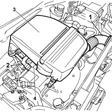
1. Intake vent
2. Oil vapour recovery hose
3. Air filter casing
4. Intake manifold
Intake manifold
The intake manifold, made from plastic material, has a shape that guarantees the correct swirl of the airflow entering so that the optimum mixture of injected fuel and aspirated air is obtained.
The following figure shows the rear of the intake manifold.
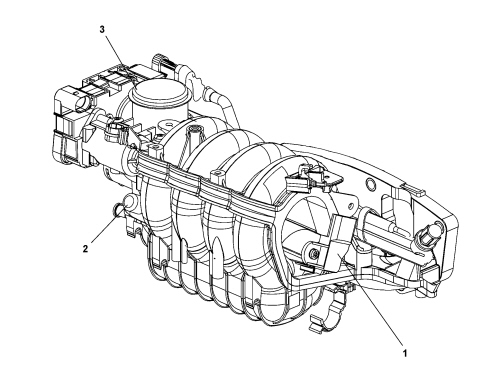
1. Temperature and air pressure sensor inside the manifold
2. Intake vacuum pump for brake servo
3. Air intake (throttle body)
The following figure shows the front of the intake manifold (engine side).
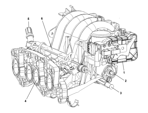
1. Throttle body
2. Fuel vapour intake valve from canister
3. Oil vapour intake duct (blow-by)
4. Intake air ducts in cylinder head
5. Fuel manifold
6. Injector control wiring
STRUCTURE
AIR SUPPLY SYSTEM
The following figure shows the section of the air supply circuit under vacuum (upstream of the turbocharger).
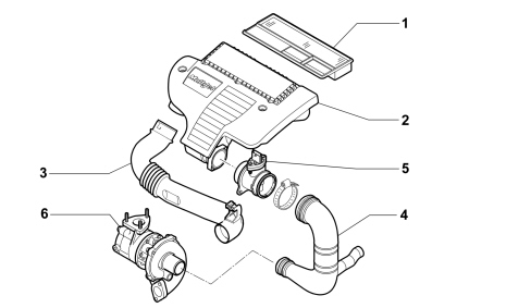
1. Filter element
2. Air filter casing
3. Air intake vent
4. Rigid pipe from air filter casing to turbocharger
5. Air flow meter
6. Turbocharger
The following figure shows the section of the air supply circuit under pressure (downstream of the turbocharger).
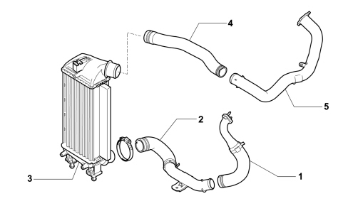
1. Air outlet pipe from turbocharger
2. Intermediate inlet pipe to the intercooler
3. Intercooler
4. Intermediate outlet pipe from the intercooler
5. Air inlet pipe to intake manifold
Parts & tools for this job For 2007 Fiat 500
- PARTEngine gasket setSearch: Fiat 500 2007 engine gasket set
- TOOLTorque wrenchSearch: 3/8 inch torque wrench
- TOOLFeeler gauge setSearch: feeler gauge set
Links open Amazon search results in a new tab. As an Amazon Associate I earn from qualifying purchases.