
Introduction - turbocharger assembly
- Make
- Fiat
- Model
- 500 Factory Service Manual
- Year
- 2007–2024
- Section
- Engine supercharging system › Introduction - turbocharger assembly
INTRODUCTION - TURBOCHARGER ASSEMBLY
DESCRIPTION OF COMPONENTS
Turbocharger (1) is connected to the exhaust manifold; it is designed to increase the volumetric efficiency of the engine.
It consists essentially of two impellers fitted to the same shaft, which turns on floating bearings that are lubricated by a branch (3) of the engine lubrication circuit.
The following figure shows the turbocharger for the version with lambda sensor.
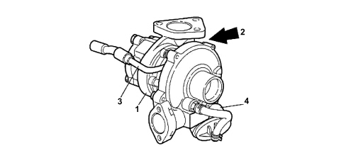
1. Turbocharger
2. Waste gate
3. Lubrication circuit branch
4. Pneumatic actuator
The following figure shows the turbocharger for the version with DPF.
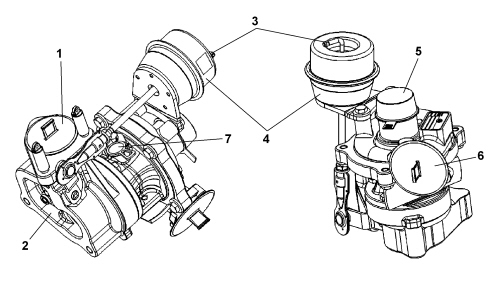
1. Exhaust gas inlet in turbine.
2. Exhaust gas outlet from turbine
3. Connector for pneumatic actuator control
4. Pneumatic actuator
5. Air inlet into the compressor
6. Air outlet from the compressor
7. Lubrication circuit branch
This oil used dissipates part of the great quantity of heat yielded by the exhaust gases to the turbine. The turbocharger is fitted with a wastegate valve (2) controlled by pneumatic actuator (4) that cuts off part of the exhaust gas flow to the turbine.
In the version with lambda sensor, the pneumatic actuator is directly operated by the pressurised air based on the pressure value reached at the compressor outlet; in the version with DPF, the pneumatic actuator is managed from the engine management control unit via the control solenoid.
Parts & tools for this job For 2007 Fiat 500
- PARTEngine gasket setSearch: Fiat 500 2007 engine gasket set
- TOOLTorque wrenchSearch: 3/8 inch torque wrench
- TOOLFeeler gauge setSearch: feeler gauge set
Links open Amazon search results in a new tab. As an Amazon Associate I earn from qualifying purchases.