
Turbocharging pressure solenoid (pierburg) valve operation check
- Make
- Fiat
- Model
- 500 Factory Service Manual
- Year
- 2007–2024
- Section
- Engine supercharging system › Turbocharging pressure solenoid (pierburg) valve operation check
TURBOCHARGING PRESSURE SOLENOID (PIERBURG) VALVE OPERATION CHECK
| STEP | CHECK TO BE PERFORMED | REMEDIAL ACTION IF THE CHECK IS NOT OK |
|---|---|---|
| 1 | Solenoid valve resistance check Disconnect the wiring from the solenoid Check that the resistance between the two solenoid terminals is 16 ohm ±10% at 20 °C | Replace the turbopressure control solenoid valve Op. 1064B38 WASTE GATE SUPERCHARGING PRESSURE ADJUSTMENT SOLENOID VALVE - R.R. |
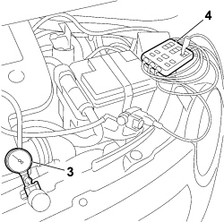
| 2 | Solenoid valve ducts check Connect pressure/vacuum pump ( 3 ) n.° 2000015500 to connector A of the turbocharging pressure solenoid Operate the pump at a vacuum below 0.50 bar (to prevent damaging the solenoid valve) Check that the flow of air between connectors A and B is impeded (internal passage closed) Connect the terminals of the solenoid to a 12 volt battery using disconnector (4) AD 233 N° 1806387000 Operate the pump at a vacuum below 0.50 bar (to prevent damaging the solenoid valve) Check that nothing is preventing the flow of air between connectors A and B (internal passage open) | Replace the turbopressure control solenoid valve Op. 1064B38 WASTE GATE SUPERCHARGING PRESSURE ADJUSTMENT SOLENOID VALVE - R.R. |
| 3 | Pressure control solenoid valve signal check Connect an Examiner in Voltmeter mode Connect disconnector (4) AD 233 N° 1806387000 across the solenoid and the wiring Insert the red probe at pin 2 of the disconnector and the black probe at pin 1 of the disconnector Set the Examiner time base at 2 seconds and 20 V f.s.d. Start the engine Check for a square wave signal as illustrated in the graph | Restore the continuity of the wiring between the engine control unit and the solenoid Restore the correct power supply to the solenoid See E5050 DIESEL ENGINES ELECTRONIC MANAGEMENT If the signal is interrupted at the control unit output. Replace the engine control unit |
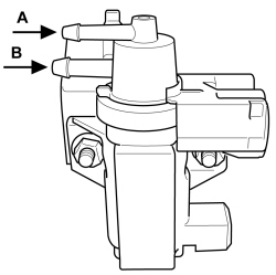
Pierburg solenoid
A. Vacuum inlet (from the vacuum pump)
B. Vacuum outlet (to the waste gate)
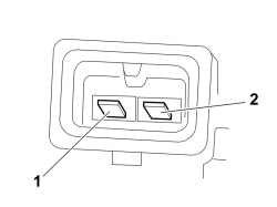
| Pierburg solenoid connector | |
|---|---|
| Pin | Function |
| 1 | Solenoid control signal |
| 2 | + 12 Power supply |
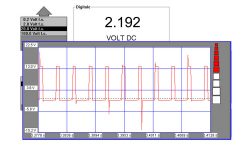
Turbocharging pressure control solenoid operation signal
Parts & tools for this job For 2007 Fiat 500
- PARTEngine gasket setSearch: Fiat 500 2007 engine gasket set
- TOOLTorque wrenchSearch: 3/8 inch torque wrench
- TOOLFeeler gauge setSearch: feeler gauge set
Links open Amazon search results in a new tab. As an Amazon Associate I earn from qualifying purchases.