
Audio system
- Make
- Fiat
- Model
- Bravo Factory Service Manual
- Year
- 2007–2014
- Section
- Accessories › Audio system
AUDIO SYSTEM
AUDIO SYSTEM
The are three different levels of acoustic system available on the vehicle:
- standard radio (with CD / MP3 player), completes the audio system with 6 speakers;
- INTERSCOPE Hi-Fi sound system (with 8 speakers, subwoofer and multi-channel amplifier);
- aftermarket radio preparation.
There is also the possibility of a Blue&Me telematic system with Bluetooth radio telephone function and Mediaplayer,
See descriptions 5580M ON-BOARD NAVIGATOR
or a Connect Nav + radiophone-navigator
See descriptions 5580P CONNECT PANEL
General specifications of the standard system
The system comprises of 6 speakers as illustrated in the diagram:
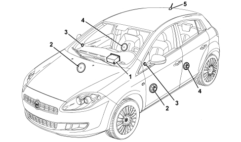
1 - Radio
2 - Front door midwoofer speakers
3 - Tweeter front speakers
4 - Midwoofer rear speakers
5 - Aerial
Front speakers
They are 165 mm diameter 40W mid-woofer speakers located in the front doors.
They are designed for the reproduction of medium-low frequencies.
The (water resistant) technology used for these components allows them to withstand possible sprays of water inside the door without being damaged.
There is a speaker with a paper cone, polyurethane support, ferrite magnet and aluminium/paper coil support.

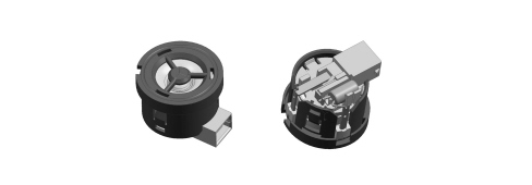
Front tweeters
These are 30W tweeter speakers located in the door panel triangular upper trim, designed to reproduce higher frequencies.
There is a dome tweeter with a polycarbonate cone, plastic support, ferrite magnet and copper coil support.
Rear speakers
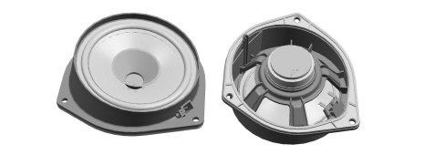
These are 130 mm diameter full-range 40W speakers, located in the rear doors, capable of reproducing the entire audio frequency spectrum.
Water resistant technology has been adopted for these components as well.
There is a dual cone speaker with a paper cone, plastic (ABS) support, ferrite magnet and aluminium coil support.
Aerial
The aerial mounting, located at the back of the vehicle roof, has a coaxial cable for transmitting the radio signal and a supply line.
The aerial stem is 36 cm long.
On some versions the aerial has three functions:
- AM and FM radio
- GSM for radiophone
- GPS for satellite navigation system.
The coaxial cable has an extension included in the vehicle rear and dashboard wiring which reaches the radio itself.
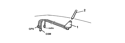
GPS - connection with GPS device
GSM - connection with GSM aerial
radio - connection with AM-FM aerial
1 - aerial mounting
2 - triple function outside aerial
Interscope hi-fi sound system
An INTERSCOPE Hi-Fi Sound System is available on request.
The Interscope audio system is characterised by an aggressive sound specifically aimed to please young people.
The system is composed of 8 speakers, a power amplifier and a subwoofer box for deep bass.
The system has been developed ad hoc for the vehicle: the acoustic properties of the passenger compartment have been carefully studied so that the amplifier and the speakers are ideally suited to the vehicle: optimum listening is available in any part of the passenger compartment.
Front speakers
These are 165 mm diameter mid-woofer speakers, with a polypropylene membrane for clean mid-range frequencies and precise bass; the power is 30 Wrms.
There are positioned in the front doors.
Front and rear tweeters
These are Tweeters with neodymium magnets and treated silk membranes for crystaline treble; the power is 20 Wrms.
The front speakers are located in the door panel upper triangular trim.
The rear speakers are located in the door above the mid-woofer speaker.
Rear speakers
These are 130 mm diameter mid-woofer speakers, with copper rings for acoustics without distortion; the power is 30 Wrms.
They are located in the rear door.
Subwoofer with amplifier
The 10 litre volume bass-reflex type sub-woofer box contains a 165 mm diameter 100W speaker for the reproduction of low frequencies.
The box is located in the luggage compartment, left wheel arch side, and also contains the 4+1 channel power amplifier (4 x 20 WRMS) for the operation of the actual subwoofer and, via two parametric equalizers, the two front channels and the two rear ones.
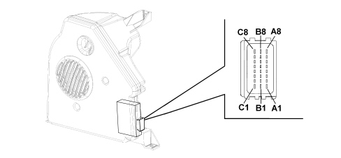
AMPLIFIER CONNECTION PIN OUT
| PIN | SIGNAL |
|---|---|
| A1 | not connected |
| A2 | Left rear speaker (output) (+) |
| A3 | Left rear speaker (output) (-) |
| A4 | Right rear speaker (output) (+) |
| A5 | Right front speaker (output) (-) |
| A6 | Left front speaker (output) (+) |
| A7 | Left front speaker (output) (-) |
| A8 | not connected |
| B1 | not connected |
| B2 | Right rear speaker (output) (+) |
| B3 | Right rear speaker (output) (-) |
| B4 | Right rear speaker (input) (-) |
| B5 | Left rear speaker (input) (-) |
| B6 | Right front speaker (input) (-) |
| B7 | Left front speaker (input) (-) |
| B8 | not connected |
| C1 | Chassis earth |
| C2 | Subwoofer amplifier power supply enablement from radio system |
| C3 | Subwoofer amplifier status recognition positive signal for specific acoustic setting |
| C4 | Right rear speaker (input) (+) |
| C5 | Left rear speaker (input) (+) |
| C6 | Right front speaker (input) (+) |
| C7 | Left front speaker (input) (+) |
| C8 | +battery power supply from F32 |
Car radio preparation trim level
The vehicle can be fitted, on request, with a simple AFTERMARKET preparation, (opt. 082) that includes the same speakers and connections as the standard version, but does NOT include the car radio which can be fitted in the aftermarket.
The radio installed in the aftermarket is therefore not a CAN network node through which information is exchanged with the Body Computer and with the other electronic units.
Two connections are supplied: one (connector A of P20) with the following standard ISO pin out:
| Pin | Function |
|---|---|
| 1 | mute (n.c.) |
| 2 | n.c. |
| 3 | n.c. |
| 4 | direct power supply |
| 5 | aerial supply (n.c.) |
| 6 | control lighting |
| 7 | ignition-operated power supply +15 |
| 8 | earth |
The second connection (connector B of P20) for connection with the speakers is the same as the standard version.
Speakers and aerial
These are the same as the standard version.
RADIO
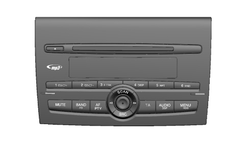
The Radio Receiver Node (RRN) is in a DIN housing, usually located in the middle of the dashboard.
There are two versions: Radio CD, and Radio CD/MP3.
Both have a painted front section: the trim is black metal and the buttons are grey.
All versions are prepared for connection with the low speed CAN interface at the B-CAN to allow dialogue with the other system nodes. The following are transferred via this interface:
- Anti-theft code;
- On control (for switching-off logic);
- Speed dependent volume control;
- Lighting control;
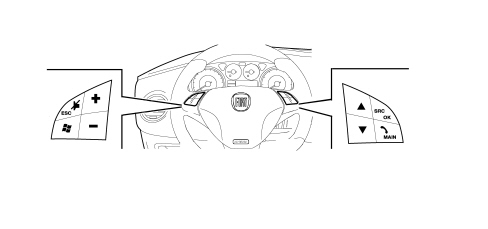
- Remote controls from the steering wheel, where fitted;
- Repetition of radio information at control panel.
Specifications
General specifications
- Music audio power: 4x40W
- 7 band graphic equalizer
- Digital tuner
- Large dimension alphanumerical display (20 characters for RDS functions + control symbol)
- Easy to manage menu for the adjustment of the radio settings and any external interfaces (I-Pod, CD-Changer, telephone)
- Mute function by pressing the volume control briefly
- Soft mute, during radio source/station changing operations
- Volume adjustment according to the vehicle speed (selected using the menu)
- Radio switching off timer adjustment (immediately or 20 minutes after the key off)
- Remote control from the steering wheel (opt.)
- Possibility of interface with external Blaupunkt CD-Changer via ASCI-BUS line
- Hi-fi system active check, where fitted
Radio specifications (radio cd and radio cd/mp3)
- High selectivity digital tuning (2IC) with SHARX function (digital selection with dynamically variable broad band)
- FM multipath detector
- Possibility of selecting HICUT function (High-Cut:= dynamic reduction of treble if RF signal is poor)
- Autostore (automatic memorizing of radio stations with best signal)
- RDS (Radio Data System) with EON, AF (alternative frequencies), TA, TP, PTY and REG function (that can be selected by the user)
- Automatic and manual search for stations
- Possibility of adjusting Local/Distance for automatic frequency search
- Possibility of programming:
. 18 FM stations (6 of which can be memorized through autostore).
. 6 MW stations
. 6 LW stations
. 6 PTY programme type stations (FM only)
- 2 scan modes (short listen to a station and automatic transfer to the next):
- Scanning the frequency band used
- Scanning programmed stations.
Cd specifications
- Motorized loading and ejection
- Pause
- Select previous/next track
- FF/F-REW
- TPM function (Track Program Memory) for 30 CDs with 40 tracks each
- Track scan function
- Mix function (random reproduction)
- Track repeat function
- CD Naming (8 characters for 30 CDs)
- CD display (display of the name of the disc/track time elapsed)
- Reading of printed audio CDs, CD-R and CD-RW
Mp3 cd specifications
- Motorized loading and ejection
- MP3-Info function (ID3-TAG)
- Select previous (next) track
- Up/down track selection
- Pause
- FF/F-REW
- Track scan function
- Mix function (random reproduction of tracks in a file/on the entire disc)
- Repeat function (of a single track or a single file)
- MP3 Display (file, ID3-TAG information, track time elapsed, name of the file)
- Reading of printed audio or information CDs, CD-R and CD-RW.
Audio specifications
- Bass
- Treble
- Balance
- Fader
- Loudness
- 7 band graphic equalizer: Preset (default), Rock, Jazz, Classic, User (can be personalized)
- Audio input for Blaupunkt CD-CHANGER.
Blaupunkt 10 disc cd changer specifications
Preparation for a 10 disc Blaupunkt CD Changer can be requested.
FIAT provides the customer with wiring from the radio to the luggage compartment; the customer must then buy the component in the aftermarket and place it at their discretion.
The Blaupunkt CD Changer features the following:
- Motorized loading and ejection
- CD selection (up & down)
- Track selection (up & down)
- Pause
- FF/F-REW
- Scan function
1.4 16v
1.4 16v
- Mix function (CD - magazine)
- TPM function (Track Program Memory)
- CD Naming (8 characters for 30 CDs).
Radio front section
Display
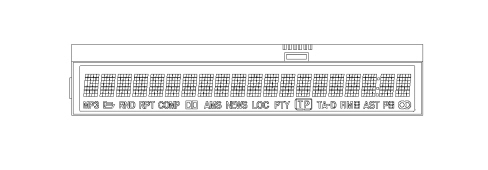
The alphanumerical display is large with 20 characters for RDS functions and control symbols
Remote controls on the steering wheel
There may be remote controls on the steering wheel for the radio:
Anti-theft code
The radio is installed in production and is connected to the CAN in order to establish communication with the Body Computer memorizing an anti-theft code known as an Exchange Code.
At each subsequent Key On (and even if the battery is disconnected), an automatic authentication procedure is repeated: the words "CAN CHECK" appear in the radio display: if the Exchange Code check is positive, the system begins to operate. If the codes compared are not the same, a message appears on the display asking the user to enter a manual code (Master Code - 4-figure code from 1111 to 6666) that is shown on the radio code card.
The Master Code is pre-programmed in production and different for each radio; it is also different from the Exchange Code.
Entering the secret code
When the radio is switched on, if there is a code request, the word "CODE" will appear on the display for about 2 seconds followed by four dashes "----".
The secret code is made up of four digits between 1 and 6, each corresponding to one of the dashes.
To enter the first digit of the code, press the button corresponding to the pre-selection stations (from 1 to 6). Enter the other digits of the code in the same way.
If the four figures are not entered within 20 seconds, the display again shows the message "CODE" for 2 seconds and then the four dashes "---". This is not considered as incorrect entering of the code.
After entering the fourth digit (within 20 seconds), the car radio will start to work.
If an incorrect code is entered, the radio will give out an acoustic warning, the word "CODE" will appear on the display for 2 seconds and then four dashes "----" to indicate that the user needs to enter the correct code.
After three attempts the radio considers the last code as "incorrect"; each time the user enters an incorrect code, the waiting time increases gradually (1 min, 2 min, 4 min, 8 min, 16 min, 30 min, 1h, 2h, 4h, 8h, 16h, 24h) to a maximum of 24 hours. The waiting time is shown on the display with the words "RADIO BLOCKED, WAIT".
After the writing has disappeared it is possible to start the procedure of entering the code again.
Code card
This document certifies ownership of the car radio. The Code Card shows the radio model, serial number and secret code.
The manual Master Code input procedure is necessary only if: replacing the Body Computer for a radio already used on another vehicle with a CAN.
A "new" radio (never previously fitted on other vehicles) can be fitted following an automatic authentication procedure without manually entering the Master Code.
Operation at key off
The following function can be selected using the radio setup menu:
- if the radio is on at the time of the Key off, it is automatically switched off after 20 minutes (or another period that can be selected using the Menu); it is, however, possible to keep it on for another 20 minutes by pressing the ON button again.
The following can be selected in the setup menu under the item "- - - I G N I T I O N - T I M E R - - -".
"- - O F F - A F T E R - 0 0 - M I N - -"
"- - O F F - A F T E R - 20 - M I N - -"
Connectors
Rear view:
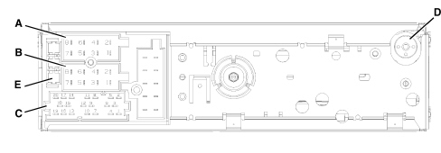
A - Supply connector
B - Speaker output connector
C - Auxiliary functions connector
D - Aerial connection
E - 10 A fuse
Connector pin out
Connector A:
| Pin | Function |
|---|---|
| A1 | B Can B (high) |
| A2 | Subwoofer amplifier status recognition positive signal for specific acoustic setting. |
| A3 | B Can A (low) |
| A4 | N.C. |
| A5 | Power supply from radio for subwoofer enablement |
| A6 | N.C. |
| A7 | +ignition power supply from F51 |
| A8 | Earth |
Connector B:
| Pin | Function |
|---|---|
| B1 | Right rear speaker + |
| B2 | Right rear speaker - |
| B3 | Right front speaker + |
| B4 | Right front speaker - |
| B5 | Left front speaker + |
| B6 | Left front speaker - |
| B7 | Left rear speaker + |
| B8 | Left rear speaker - |
Connector C/D/E:
| Pin | Function |
|---|---|
| C1 | LH AUX signal. |
| C2 | RH AUX signal. |
| C3 | AUX signal |
| C4 | N.C. |
| C5 | N.C. |
| C6 | Power suppy from radio for amplifier on aerial (N.C.) |
| D7 | Audio in telephone + (N.C.) |
| D8 | Audio in telephone - (N.C.) |
| D9 | Telephone mute (N.C.) |
| D10 | Steering wheel controls 1 (N.C.) |
| D11 | Steering wheel controls 2 (N.C.) |
| D12 | Earth for external connections (N.C.) |
| E13 | CDC data IN |
| E14 | CDC data OUT |
| E15 | Permanent power supply for CDC |
| E16 | Positive signal for CDC power supply enablement |
| E17 | CDC data GND |
| E18 | CDC audio GND |
| E19 | L input for CDC |
| E20 | R input for CDC |
Parts & tools for this job For 2007 Fiat Bravo
- TOOLDigital multimeterSearch: automotive digital multimeter
- PARTAssorted fuse kitSearch: car fuse assortment kit
- TOOLWire crimper and connector kitSearch: wire crimper connector kit
Links open Amazon search results in a new tab. As an Amazon Associate I earn from qualifying purchases.