
Connector A
- Make
- Fiat
- Model
- Bravo /Brava (182) Factory Service Manual
- Year
- 1995–2001
- Section
- Fuel system (1747 16v) › Connector A
10 EngineConnector A
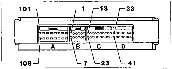
* Short circuited at pin 9 for versions without climate control
Connector A
- Operation of injector for cylinder 1
- N.C.
- Operation of injector for cylinder 2
- Pump relay operation
- Operation of injector for cylinder 3
- Negative for charcoal filter solenoid valve
- Earth
- Earth
- Negative for engine idle adjustment solenoid valve
- Operation of injector for cylinder 4
- Positive for engine idle adjustment solenoid valve
- Control unit supply
- Climate control compressor relay feed (if fitted)
- N.C.
- N.C.
- Earth
Connector B
- Operation of coil for cylinder 1
- Operation of coil for cylinder 3
- Operation of rev counter
- N.C.
- N.C.
- Earth
- Operation of coil for cylinder 3
- Operation of coil for cylinder 4
- Operation of electric fan low speed relay
- Operation of electric fan high speed relay *
- Operation of system failure light
- Earth
Connector C
- N.C.
- Positive for air flow meter
- Positive for coolant temperature sensor
- Positive for Lambda sensor
- Signal for three stage pressure switch (if fitted)
- N.C.
- N.C.
- Connection with FIAT CODE
- Positive for detonation sensor
- Negative for air flow meter
- Line K
- N.C.
- Signal for butterfly position sensor
- Negative for lambda sensor
- N.C.
- Signal for engaging compressor (if fitted)
- A/V signal from ignition switch (+50)
- N.C.
- Earth for detonation sensor
- Negative for coolant temperature and butterfly position
Connector D
- Positive for engine rpm sensor
- Positive for engine timing sensor
- Earth for engine rpm sensor
- Signal for vehicle speed sensor
- Positive for butterfly position sensor
- N.C.
- Control unit supply
- Earth
- Negative for engine rpm sensor
- Negative for engine timing sensor
- N.C.
- Calibration selection
- Trim level selection (to earth for versions without climate control)
- Control unit supply
- Control unit supply
- Earth
Parts & tools for this job For 1995 Fiat Bravo
- PARTFuel filterSearch: Fiat Bravo 1995 fuel filter
- TOOLFuel pressure test kitSearch: fuel pressure test kit
- TOOLFuel line disconnect toolSearch: fuel line disconnect tool
Links open Amazon search results in a new tab. As an Amazon Associate I earn from qualifying purchases.