
Hitachi system wiring diagram key
- Make
- Fiat
- Model
- Bravo /Brava (182) Factory Service Manual
- Year
- 1995–2001
- Section
- Fuel system (1747 16v) › Hitachi system wiring diagram key
10 EngineHitachi system wiring diagram key
Hitachi system wiring diagram key
- Engine control unit
- F/L Tester (line K)
- Engine timing sensor
- Lambda sensor
- Air flow meter
- Ignition coils
- Ignition power module
- Butterfly position sensor
- Coolant temperature sensor
- Detonation sensor
- Engine rpm sensor
- Control unit casing earth on vehicle bodyshell
- Vehicle speed inlet
- Intake from three stage pressure switch (climate control if fitted)
- Calibration selection
- Trim level selection (to earth for versions without climate control)
- Connection with Fiat CODE control unit
- Operation of electric fan low speed relay
- Operation of electric fan high speed relay (short circuited at pin 9 for versions without climate control)
- Intake for request to engage climate control compressor (if fitted)
- Operation of rev counter
- Climate control compressor relay feed (if fitted)
- Operation of system failure light
- Engine idle speed adjustment sol. valve
- Injectors
- Charcoal filter solenoid valve
- Inertia switch
- Electric fuel pump
- Electric fuel pump relay
- System relay feed
- AVV signal from ignition key (+50)
- Supply from battery (+30)
- Supply from ignition key (+15)
- Pump fuse (30 A)
- System fuse (15 A)
- Earth (on engine block)
- Earth (under cylinder head cover)
SYSTEM RELAYS
With the ignition key in the ON position (+15) the energizing coils for both relays are supplied, which close the respective power contacts.
Relay (A) supplies the electric fuel pump, receiving voltage directly from the battery.
Relay (B) ensures the multiple supply of the control unit and the various system sensors and actuators, both directly and via the connectors.
NOTE The layout of relays (A) and (B) and fuses (7) and (8) can vary through production requirements. They should be recognized on the basis of the electrical connections.
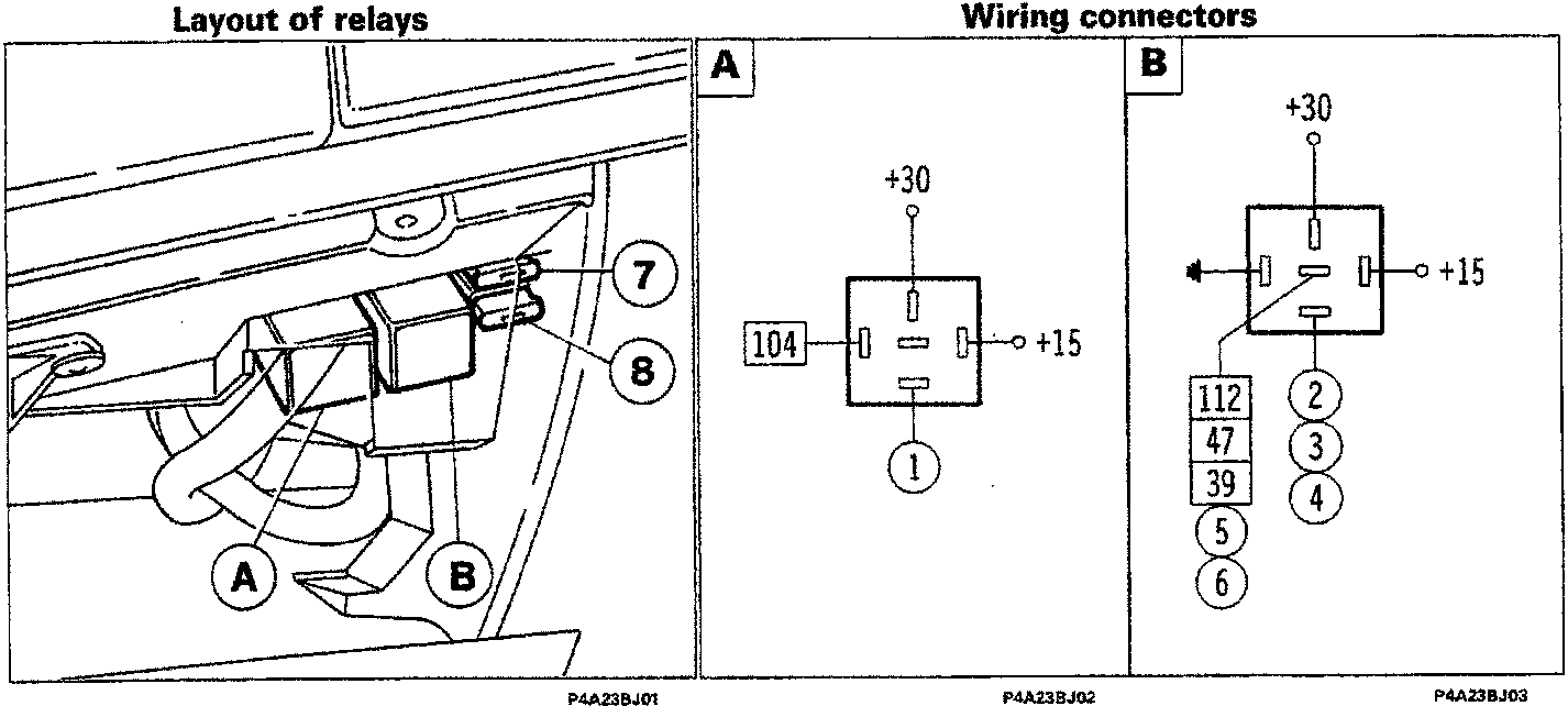
- Electric fuel pump
- Injectors
- Charcoal filter solenoid valve
- Ignition power module
- Air flow meter
- Butterfly position sensor
- Fuse
- Fuse
- A. Electric fuel pump relay
- B. System relay feed
Parts & tools for this job For 1995 Fiat Bravo
- TOOLDigital multimeterSearch: automotive digital multimeter
- PARTAssorted fuse kitSearch: car fuse assortment kit
- TOOLWire crimper and connector kitSearch: wire crimper connector kit
Links open Amazon search results in a new tab. As an Amazon Associate I earn from qualifying purchases.