
Operating principle
- Make
- Fiat
- Model
- Bravo /Brava (182) Factory Service Manual
- Year
- 1995–2001
- Section
- Fuel system (1747 16v) › Operating principle
Operating principle
The anti-evaporation system has the aim of preventing the fuel vapours, made up of the lightest parts of the hydrocarbons which basically form in the tank, from being discharged into the atmosphere. The system operates, above all at high outside temperatures when the temperature of the fuel increases and consequently the tendency towards evaporation increases: in this situation there is an increase in the pressure inside the tank.
In particular, even with the tank (1) full, with the vehicle stationary the two float valves (3) remain open as they are located higher than the breather pipe and therefore they allow the vapours to reach the separator (2) from where they mainly return to the tank as they condense.
If, on the other hand, there is strong splashing when the vehicle is driving or it overturns, the valves (3) close preventing fuel from escaping.
When the pressure inside the tank reaches about 30-40 mbar, the multi-purpose valve (8) opens and the fuel vapours reach the charcoal filter (6). The valve (8) also allows an intake of air into the tank through the charcoal filter if necessary following the lowering of the level of fuel and the consequent vacuum which is created inside the tank.
When the engine is running, the control unit operates the charcoal filter solenoid valve which allows the intake of vapours by the engine and the consequent scavenging of the charcoal filter.
If as a result of the malfunction of one of the components, the pressure inside the tank increases to dangerous levels, the safety valve located in the cap (4) allows the pressure to be discharged outwards. If necessary, this valve can open in the opposite direction, to ventilate the tank and prevent the vacuum reaching excessive values.
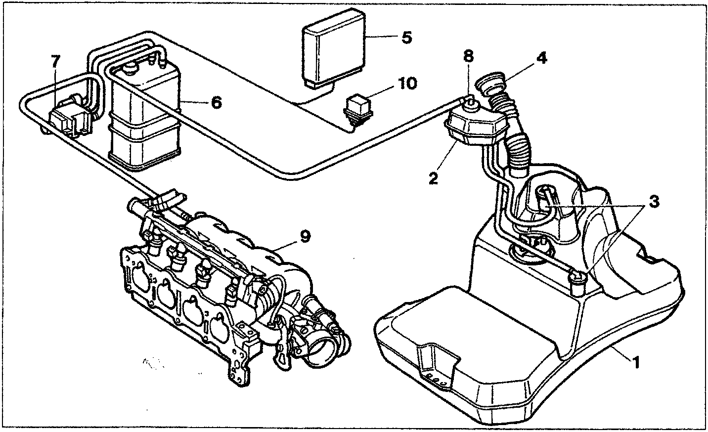
- Fuel tank
- Vapour separator
- Float valve
- Cap with safety valve
- Engine control unit
- Charcoal filter
- Charcoal filter solenoid valve
- Multi-purpose valve
- Inlet manifold
- Relay
Parts & tools for this job For 1995 Fiat Bravo
- PARTFuel filterSearch: Fiat Bravo 1995 fuel filter
- TOOLFuel pressure test kitSearch: fuel pressure test kit
- TOOLFuel line disconnect toolSearch: fuel line disconnect tool
Links open Amazon search results in a new tab. As an Amazon Associate I earn from qualifying purchases.