
Sensors
- Make
- Fiat
- Model
- Bravo /Brava (182) Factory Service Manual
- Year
- 1995–2001
- Section
- Fuel system (1747 16v) › Sensors
Sensors
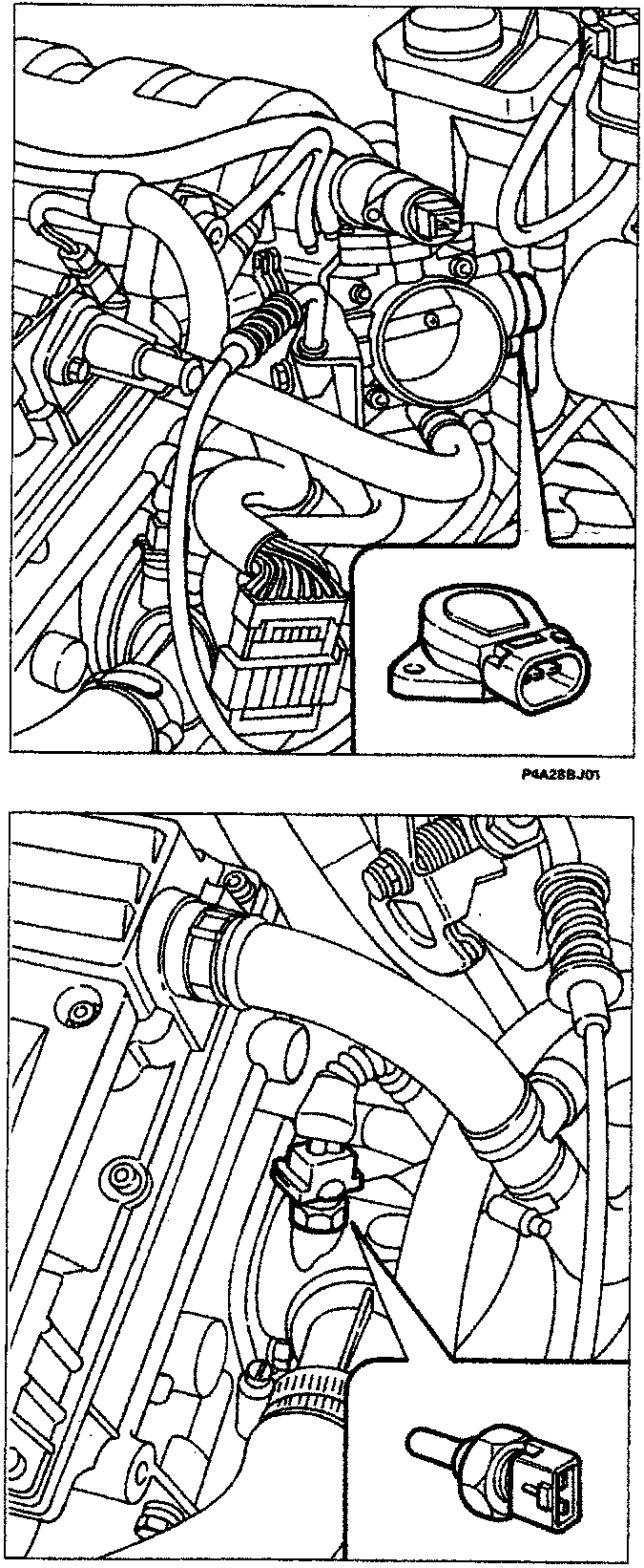
P4A2BBJ01
P4A2BBJ03
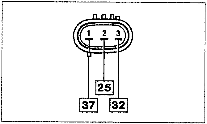
Wiring connector
BUTTERFLY POSITION SENSOR
It is made up of a single track potentiometer where the moving part is rotated by the accelerator butterfly shaft.
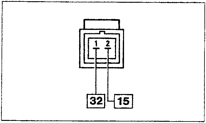
Wiring connector
P4A2BBJ02
COOLANT TEMPERATURE SENSOR
The sensor is fitted on the thermostat. It is made up of a brass casing which protects the resistive element made up of an NTC (Negative Temperature Coefficient) thermistor where the electrical resistance decreases as the temperature increases.
The reference voltage is 5 Volt: since the control unit input circuit is designed as a voltage divider, the reference voltage is shared between a resistance in the control unit and the actual sensor.
As a result the control unit is capable of evaluating the variations in the sensor resistance through the changes in voltage.
P4A2BBJ04
Parts & tools for this job For 1995 Fiat Bravo
- TOOLOBD2 scannerSearch: OBD2 scanner
- TOOLDigital multimeterSearch: automotive digital multimeter
- TOOLBack-probe test leadsSearch: back probe test leads
Links open Amazon search results in a new tab. As an Amazon Associate I earn from qualifying purchases.