
Intake circuit
- Make
- Fiat
- Model
- Bravo /Brava (182) Factory Service Manual
- Year
- 1995–2001
- Section
- Fuel system (1747 16v) › Intake circuit
10 EngineIntake circuit
INTAKE CIRCUIT
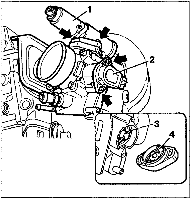
NOTE When refitting the butterfly position sensor, take care that the operating lever fitted on the butterfly shaft (3) is above the sensor driving element (4), as shown in the diagram.
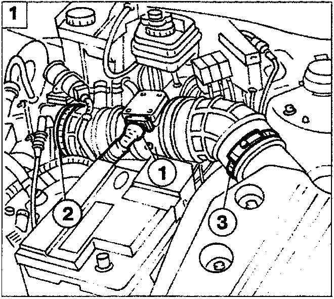
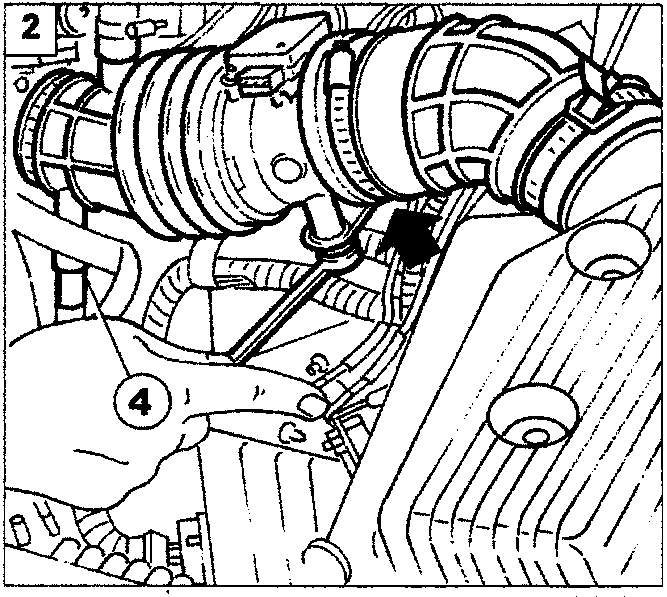
Removing-refitting air flow meter
- Remove the battery, disconnect the electrical connector (1) from the meter, loosen the bands (2) and (3) fixing the inlet sleeve;
- disconnect the blow-by sleeve (4) from the inlet sleeve, undo the two bolts (arrow) fixing the flow meter mounting bracket and remove the assembly; then loosen the bands at the flow meter and re-move the two sleeves.
Parts & tools for this job For 1995 Fiat Bravo
- TOOLDigital multimeterSearch: automotive digital multimeter
- PARTAssorted fuse kitSearch: car fuse assortment kit
- TOOLWire crimper and connector kitSearch: wire crimper connector kit
Links open Amazon search results in a new tab. As an Amazon Associate I earn from qualifying purchases.