
Engine RPM sensor
- Make
- Fiat
- Model
- Bravo /Brava (182) Factory Service Manual
- Year
- 1995–2001
- Section
- Fuel system (1747 16v) › Engine RPM sensor
ENGINE RPM SENSOR
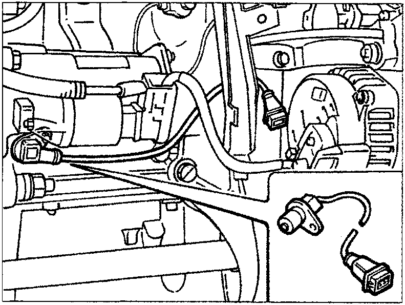
The sensor is fixed to the cylinder block-/crankcase: the flywheel is fixed with a crankshaft crank.
Operating principle
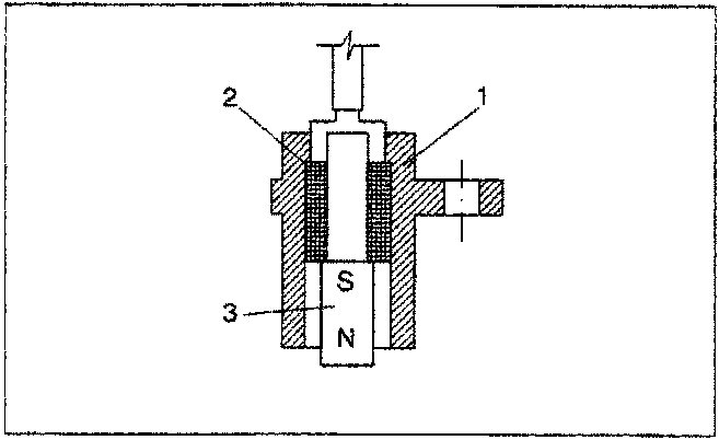
The sensor is made up of a tubular casing (1) which houses a permanent magnet (3) and an electrical winding (2).
As a result of the flywheel teeth passing by, the magnetic flow produced by the magnet (3) undergoes oscillations resulting from the variation of the gap.
These oscillations create an electro-motive force in the winding (2) which produces a voltage which is alternatively positive (tooth facing the sensor) and negative (gap facing the sensor): see paragraph on "signal management". The peak sensor output voltage depends, with other factors being equal, on the distance between the sensor and the tooth (gap).
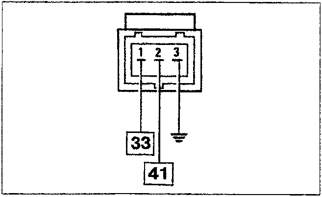
Wiring connector
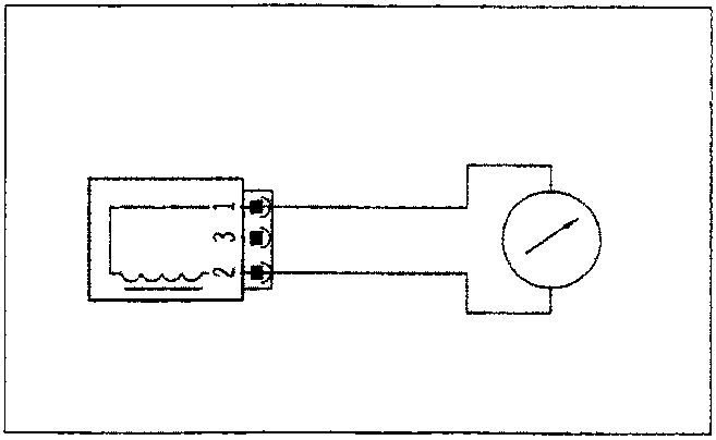
The resistance of the sensor can be measured by disconnecting the connector and connecting an ohmmeter to the sensor
Resistance: 570 ± 57 ohm at 20°C
Parts & tools for this job For 1995 Fiat Bravo
- TOOLOBD2 scannerSearch: OBD2 scanner
- TOOLDigital multimeterSearch: automotive digital multimeter
- TOOLBack-probe test leadsSearch: back probe test leads
Links open Amazon search results in a new tab. As an Amazon Associate I earn from qualifying purchases.