
Vehicle speed sensor
- Make
- Fiat
- Model
- Bravo /Brava (182) Factory Service Manual
- Year
- 1995–2001
- Section
- Fuel system (1747 16v) › Vehicle speed sensor
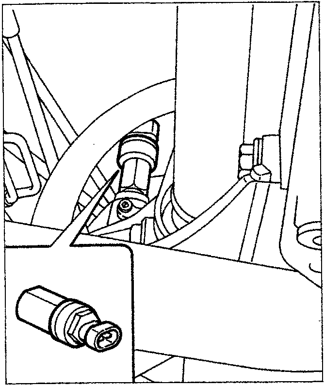
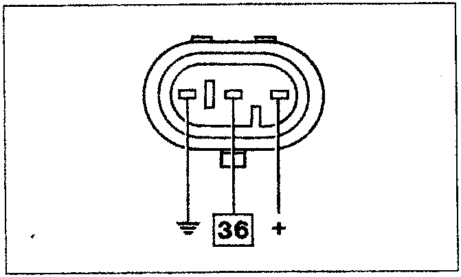
Wiring connector
VEHICLE SPEED SENSOR
The sensor is positioned on the differential outlet, by the left drive shaft coupling and transmits the information relating to the vehicle speed to the control unit: the signal is also used for the operation of the speedometer.
The sensor is the Hall effect type (see "engine timing sensor" paragraph) and it is calibrated so that for each impulse there is a corresponding travel of one metre: on the basis of the frequency of the impulses it is therefore possible to know the speed of the vehicle.
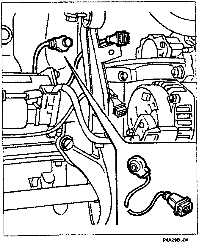
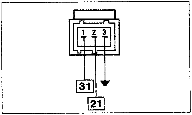
Wiring connector
DETONATION SENSOR
This sensor is the piezoelectric type and is fitted on the engine crankcase in a symmetrical position in relation to the pairs of cylinders 1-2 and 3-4.
This position is determined by the need to detect the start of detonation similarly for all cylinders.
When there is detonation, vibrations of a particular frequency are created in the crankcase which are transformed by the sensor into a signal whose voltage is proportional to their intensity.
Parts & tools for this job For 1995 Fiat Bravo
- TOOLOBD2 scannerSearch: OBD2 scanner
- TOOLDigital multimeterSearch: automotive digital multimeter
- TOOLBack-probe test leadsSearch: back probe test leads
Links open Amazon search results in a new tab. As an Amazon Associate I earn from qualifying purchases.