
Vehicle speed sensor (page 2 of 2)
- Make
- Fiat
- Model
- Bravo /Brava (182) Factory Service Manual
- Year
- 1995–2001
- Section
- Fuel system (1747 16v)
10 EngineVehicle speed sensor · page 2 of 2
The ignition circuit is the static advance inductive discharge type. The power module is outside of the control unit, whilst the high tension is supplied by four ignition coils fitted directly on the spark plugs (top-plug type coils).
The primary winding for each coil is supplied by the battery voltage via the system relay and is connected to the control module for connection to earth.
The optimum ignition advance is calculated by the control unit depending on the engine speed and load and is implemented in the form of the time between the moment in which the primary circuit supply is interrupted and the explosion stroke TDC.
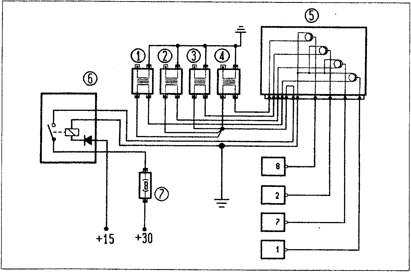
- Coil for cylinder 1
- Coil for cylinder 2
- Coil for cylinder 3
- Coil for cylinder 4
- Ignition power module
- System relay
- Fuse
Parts & tools for this job For 1995 Fiat Bravo
- TOOLOBD2 scannerSearch: OBD2 scanner
- TOOLDigital multimeterSearch: automotive digital multimeter
- TOOLBack-probe test leadsSearch: back probe test leads
Links open Amazon search results in a new tab. As an Amazon Associate I earn from qualifying purchases.