
Technical information
- Make
- Fiat
- Model
- Bravo /Brava (182) Factory Service Manual
- Year
- 1995–2001
- Section
- Radio equipment (98 range) › Technical information
TECHNICAL INFORMATION
Aerial
The vehicle is fitted with an aerial located in the roof.
Electrically operated aerial and external amplifier (available on request)
The radio is prepared for an automatic electric aerial (which comes out the moment the radio is switched on and goes back in when it is switched off) and an external amplifier.
The switching voltage for the aerial is at contact 5 (connector "A") of the radio and the switching voltage for the amplifier is at contact 3 (connector "A").
The switching voltage for both outputs is + 12 V with a maximum current of 0.5 A.
Speakers for radio equipment
The acoustic equipment consists of:
- 2 elliptical diffusers 130 x 180 mm with a power of 30 W max. each;
- 2 tweeter-dome fluid-iron diffusers with a power of 40 W max. each;
- 2 130 mm diffusers with a power of 30 W max. each.
Fuses
The radio has a 10 A protective fuse.
Connections
This paragraph describes the connector at the rear of the radio.
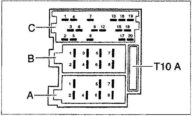
Supply voltages
Contacts at blade A:
A8 Connection for earth
Connect to terminal 31 (earth) of the vehicle.
A7 Connection for 12 V supply voltage
Connect to terminal 30 (continuous positive) of the vehicle.
A6 Connection for instrument lights
Contact not connected: no lights with radio switched off if the instrument lights are switched on.
A5 12 V switching voltage output (max 0.5 A)
Present at the contact at blades A5 when the radio is on.
For automatic aerial (extension/retraction), aerial amplifier (supply voltage) etc.
A4 Connection for ignition voltage of +12 V
Connect to terminal 15 of the vehicle, if the radio is going to be switched on and off by the ignition.
Connection A4 may also not be wired. In this case, the radio should come on and off via the VOL control.
With the engine switched off the equipment switches off after about 20 minutes
A2 Phone-Mute connection for car phone or receiver/transmitter
The radio audio function is deactivated during the operation of the car phone or receiver/transmitter.
The message "PHONE" appears on the display.
Contact A2 should be earthed from the telephone/receiver-transmitter mute outlet
A1 SCV (+) connection "for adjusting volume according to the speed."
Parts & tools for this job For 1995 Fiat Bravo
- TOOLDigital multimeterSearch: automotive digital multimeter
- PARTAssorted fuse kitSearch: car fuse assortment kit
- TOOLWire crimper and connector kitSearch: wire crimper connector kit
Links open Amazon search results in a new tab. As an Amazon Associate I earn from qualifying purchases.