
Bonnet wiring - r.r.
- Make
- Fiat
- Model
- Croma Factory Service Manual
- Year
- 2005–2010
- Section
- Instrument/gauge electrical circuits › Bonnet wiring - r.r.
BONNET WIRING - R.R.
Removing
- Turn the ignition key to the OFF position.
- Disconnect the negative battery terminal.
| Description | Connector | |
|---|---|---|
| BATTERY | See A001 BATTERY |
Op. 5530B52 BATTERY SUPPORT/DRIP TRAY - R.R
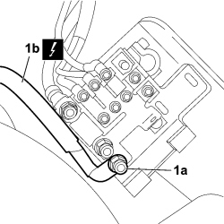
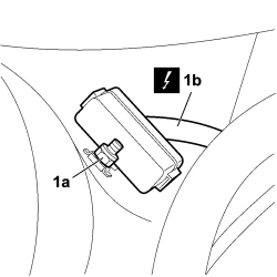
1. Unscrew nut (1a) securing the electrical connection (1b) of the starter motor to the battery connection terminal plate and disconnect the connection.
| Description | Connector | |
|---|---|---|
| 1b | MAXI FUSE BOX ON BATTERY | See B099 MAXI FUSE BOX ON BATTERY |
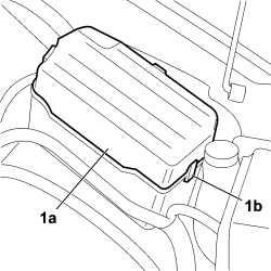
1. Remove relay and fuse compartment cover (1a) by releasing the three retaining clips (1b).
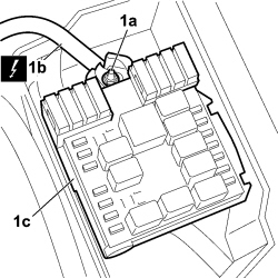
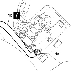
1. Undo the fixing nut (1a) for the electrical connection (1b), positive lead, to junction unit (1c), and disconnect the connection.
| Description | Connector | |
|---|---|---|
| 1b | ENGINE COMPARTMENT JUNCTION UNIT | See B001 ENGINE COMPARTMENT JUNCTION UNIT |
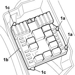
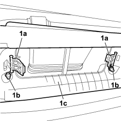
1. Prise up the two clips (1a) retaining junction unit (1b), turn forward toward the engine and prise out of the retainers on pivot pins (1c).
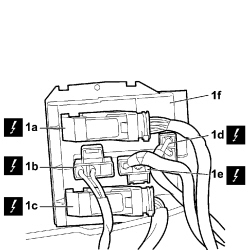
1. Release from the anchorages and disconnect electrical connections (1a) (1b) (1c) (1d) and (1e), on the underside of control unit (1f) and remove the junction unit from the vehicle.
| Description | Connector | |
|---|---|---|
| 1a | ENGINE COMPARTMENT JUNCTION UNIT | See B001 ENGINE COMPARTMENT JUNCTION UNIT |
| Description | Connector | |
|---|---|---|
| 1b | ENGINE COMPARTMENT JUNCTION UNIT | See B001 ENGINE COMPARTMENT JUNCTION UNIT |
| Description | Connector | |
|---|---|---|
| 1c | ENGINE COMPARTMENT JUNCTION UNIT | See B001 ENGINE COMPARTMENT JUNCTION UNIT |
| Description | Connector | |
|---|---|---|
| 1d | ENGINE COMPARTMENT JUNCTION UNIT | See B001 ENGINE COMPARTMENT JUNCTION UNIT |
| Description | Connector | |
|---|---|---|
| 1e | ENGINE COMPARTMENT JUNCTION UNIT | See B001 ENGINE COMPARTMENT JUNCTION UNIT |
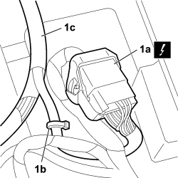
1. Release from the anchorage and disconnect electrical connection (1a) of the junction connector,disconnect and relase wiring harness (1c) from anchorage (1b).
| Description | Connector | |
|---|---|---|
| 1a | FRONT/ENGINE COUPLING | See D004 FRONT/ENGINE COUPLING |
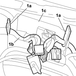
1. Remove both bulkhead couplings (1a) and release wiring harness (1b) from the control unit casing.
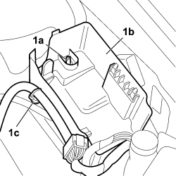
1. Undo nut (1a) securing the control unt casing (1b), disconnect and release anchorage (1c) of the wiring harness, remove the casing from the vehicle.
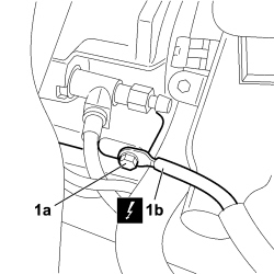
1. Undo the fixing bolt (1a) of the earth connection (1b) on the gearbox.
| Description | Connector | |
|---|---|---|
| 1b | INJECTION CONTROL UNIT EARTH | See C060 INJECTION CONTROL UNIT EARTH |
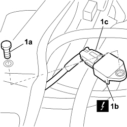
1. Unscrew bolt (1a) securing airbag sensor (1b), disconnect the sensor from the front tray, release from the anchorage and disconnect the airbag sensor electrical connection (1c).
| Description | Connector | |
|---|---|---|
| 1c | SENSOR FOR PASSENGER SIDE FRONT AIRBAG | See K175 DRIVER'S SIDE FRONT AIR BAG SENSOR |
Op. 4450B12 FRONT WHEELS (TWO) - R+R
Op. 7055B90 LEFT FRONT WHEEL ARCH LINER - R.R.
Op. 7055B91 RIGHT FRONT WHEEL ARCH LINER - R.R.
Working on the left side (driver side), disconnect the following connections:
| Description | Connector | |
|---|---|---|
| LEFT SIDE DIRECTION INDICATOR | See F020 LEFT SIDE DIRECTION INDICATOR |
| Description | Connector | |
|---|---|---|
| LEFT BRAKE PAD WEAR SENSOR (SWITCH) | See K020 LEFT BRAKE PAD WEAR SENSOR (SWITCH) |
| Description | Connector | |
|---|---|---|
| LEFT FRONT WHEEL SENSOR FOR ABS | See K070 LEFT FRONT WHEEL SENSOR FOR ABS |
| Description | Connector | |
|---|---|---|
| WINDSCREEN/REARSCREEN ELECTRIC WASHER PUMP MOTOR | See N022 WINDSCREEN WASHER/ REAR WINDOW WASHER PUMP MOTOR |
| Description | Connector | |
|---|---|---|
| HEADLAMP WASHER ELECTRIC PUMP MOTOR | See N025 HEADLAMP WASHER PUMP MOTOR |
| Description | Connector | |
|---|---|---|
| LEFT FOG LIGHT | See F015 LEFT FOG LIGHT |
| Description | Connector | |
|---|---|---|
| FRONT HEADLAMP ALIGNMENT CORRECTER POTENTIOMETER (CAF) | See K001 HEADLAMP ALIGNMENT CORRECTOR FRONT POTENTIOMETER (CAF) |
| Description | Connector | |
|---|---|---|
| HEADLAMP ALIGNMENT CONTROL UNIT (CAF) | See M073 HEADLAMP ALIGNMENT CONTROL UNIT (CAF) |
| Description | Connector | |
|---|---|---|
| LEFT HEADLAMP | See F010 LEFT HEADLAMP |
| Description | Connector | |
|---|---|---|
| TYRE PRESSURE CHECK CONTROL UNIT AERIAL | See P012 TYRE PRESSURE CONTROL UNIT ANTENNA |
| Description | Connector | |
|---|---|---|
| BRAKE FLUID LEVEL SENSOR (SWITCH) | See K025 BRAKE FLUID LEVEL SENSOR (SWITCH) |
| Description | Connector | |
|---|---|---|
| ABS FRONT EARTH | See C012 ABS FRONT EARTH |
| Description | Connector | |
|---|---|---|
| BRAKE SYSTEM CONTROL UNIT (NFR) | See M051 BRAKING SYSTEM CONTROL UNIT (NFR) |
| Description | Connector | |
|---|---|---|
| SINGLE-TONE HORN | See P005 |
Op. 7210E22 R.R. WINDSCREEN BASE TRIM
| Description | Connector | |
|---|---|---|
| WINDSCREEN WIPER MOTOR | See N015 WINDSCREEN WIPER MOTOR |
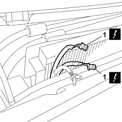
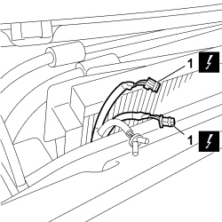
1. Disconnect both two-pin connectors of the windscreen washer nozzle demister coils.
| Description | Connector | |
|---|---|---|
| 1 | RIGHT WINDSCREEN WASHER (NOZZLE) DEMISTER COIL | See O051 RIGHT WINDSCREEN WASHER (NOZZLE) DEFROZING RESISTANCE |
| Description | Connector | |
|---|---|---|
| 1 | LEFT WINDSCREEN WASHER (NOZZLE) DEMISTER COIL | See O050 LEFT WINDSCREEN WASHER (NOZZLE) DEFROZING RESISTANCE |
1. Release the retaining clips (1a) and extract the pollen filter (1b).
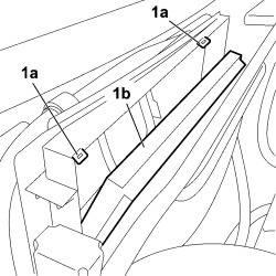
1. Releaase the two retaining clips (1a) for the pollen filter duct, undo the two nuts (1b) fixing the pollen filter duct and remove the duct (1c) from the vehicle.
1. Undo the nut (1a) on the earth connection and disconnect the earth lead (1b).
| Description | Connector | |
|---|---|---|
| 1b | LEFT FRONT EARTH | See C010 LEFT FRONT EARTH |
| Description | Connector | |
|---|---|---|
| 1b | RIGHT FRONT EARTH | See C011 RIGHT FRONT EARTH |
- Disconnect the following connections on the right side (passenger side) of the vehicle.
| Description | Connector | |
|---|---|---|
| RIGHT SIDE DIRECTION INDICATOR | See F021 RIGHT SIDE DIRECTION INDICATOR |
| Description | Connector | |
|---|---|---|
| RIGHT FRONT WHEEL SENSOR FOR ABS | See K071 RIGHT FRONT WHEEL SENSOR FOR ABS |
| Description | Connector | |
|---|---|---|
| RIGHT FOG LIGHT | See F016 RIGHT FOG LIGHT |
| Description | Connector | |
|---|---|---|
| RIGHT HEADLAMP | See F011 RIGHT HEADLAMP |
| Description | Connector | |
|---|---|---|
| SENSOR FOR PASSENGER SIDE FRONT AIRBAG | See K176 PASSENGER SIDE FRONT AIR BAG SENSOR |
| Description | Connector | |
|---|---|---|
| BONNET OPENING SWITCH | See I010 BONNET RELEASE SWITCH |
| Description | Connector | |
|---|---|---|
| TYRE PRESSURE CHECK CONTROL UNIT AERIAL | See P012 TYRE PRESSURE CONTROL UNIT ANTENNA |
| Description | Connector | |
|---|---|---|
| ADDITIONAL HEATER CONTROL UNIT | See M075 ADDITIONAL HEATER CONTROL UNIT |
| Description | Connector | |
|---|---|---|
| EXHAUST GAS SENSOR | See K064 EXHAUST GAS PRESENCE SENSOR |
| Description | Connector | |
|---|---|---|
| ALARM SIREN | See P090 ALARM SIREN |
Op. 7040A44 LEFT DASHBOARD SIDE TRIM - R.R.
Op. 7040A24 LOWER FACIA COVER TRIM - R+R
Op. 5505A35 MAIN BODY COMPUTER/JUNCTION UNIT - R.R.
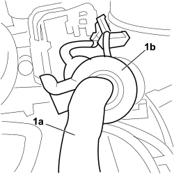
1. Remove integrated wiring (1a) from the engine compartment, prising the bulkhead coupling (1b) out of the body and withdraw carefully from the bulkhead.
Remove the integrated wiring from the vehicle.
Refitting
- Check that the wiring and the pollen filter duct are not damaged.
- Position the wiring on the vehicle and connect. Disconnect in reverse order.
| Description | Connector | |
|---|---|---|
| MAXIFUSE BOX ON BATTERY | See B099 MAXIFUSE BOX ON BATTERY |
| Description | Connector | |
|---|---|---|
| ENGINE COMPARTMENT JUNCTION UNIT | See B001 ENGINE COMPARTMENT JUNCTION UNIT |
| Description | Connector | |
|---|---|---|
| FRONT/ENGINE COUPLING | See D004 FRONT/ENGINE COUPLING |
| Description | Connector | |
|---|---|---|
| INJECTION CONTROL UNIT EARTH | See C060 INJECTION CONTROL UNIT EARTH |
| Description | Connector | |
|---|---|---|
| SENSOR FOR PASSENGER SIDE FRONT AIRBAG | See K175 DRIVER'S SIDE FRONT AIR BAG SENSOR |
| Description | Connector | |
|---|---|---|
| WINDSCREEN WIPER MOTOR | See N015 WINDSCREEN WIPER MOTOR |
| Description | Connector | |
|---|---|---|
| LEFT SIDE DIRECTION INDICATOR | See F020 LEFT SIDE DIRECTION INDICATOR |
| Description | Connector | |
|---|---|---|
| LEFT BRAKE PAD WEAR SENSOR (SWITCH) | See K020 LEFT BRAKE PAD WEAR SENSOR (SWITCH) |
| Description | Connector | |
|---|---|---|
| LEFT FRONT WHEEL SENSOR FOR ABS | See K070 LEFT FRONT WHEEL SENSOR FOR ABS |
| Description | Connector | |
|---|---|---|
| WINDSCREEN/REARSCREEN ELECTRIC WASHER PUMP MOTOR | See N022 WINDSCREEN WASHER/ REAR WINDOW WASHER PUMP MOTOR |
| Description | Connector | |
|---|---|---|
| HEADLAMP WASHER ELECTRIC PUMP MOTOR | See N025 |
| Description | Connector | |
|---|---|---|
| LEFT FOG LIGHT | See F015 LEFT FOG LIGHT |
| Description | Connector | |
|---|---|---|
| FRONT HEADLAMP ALIGNMENT CORRECTER POTENTIOMETER (CAF) | See K001 HEADLAMP ALIGNMENT CORRECTOR FRONT POTENTIOMETER (CAF) |
| Description | Connector | |
|---|---|---|
| HEADLAMP ALIGNMENT CONTROL UNIT (CAF) | See M073 HEADLAMP ALIGNMENT CONTROL UNIT (CAF) |
| Description | Connector | |
|---|---|---|
| LEFT HEADLAMP | See F010 LEFT HEADLAMP |
| Description | Connector | |
|---|---|---|
| TYRE PRESSURE CHECK CONTROL UNIT AERIAL | See P012 TYRE PRESSURE CONTROL UNIT ANTENNA |
| Description | Connector | |
|---|---|---|
| BRAKE FLUID LEVEL SENSOR (SWITCH) | See K025 BRAKE FLUID LEVEL SENSOR (SWITCH) |
| Description | Connector | |
|---|---|---|
| ABS FRONT EARTH | See C012 ABS FRONT EARTH |
| Description | Connector | |
|---|---|---|
| BRAKE SYSTEM CONTROL UNIT (NFR) | See M051 BRAKING SYSTEM CONTROL UNIT (NFR) |
| Description | Connector | |
|---|---|---|
| SINGLE-TONE HORN | See P005 SINGLE TONE HORN |
| Description | Connector | |
|---|---|---|
| RIGHT WINDSCREEN WASHER (NOZZLE) DEMISTER COIL | See O051 RIGHT WINDSCREEN WASHER (NOZZLE) DEFROZING RESISTANCE |
| Description | Connector | |
|---|---|---|
| LEFT WINDSCREEN WASHER (NOZZLE) DEMISTER COIL | See O050 LEFT WINDSCREEN WASHER (NOZZLE) DEFROZING RESISTANCE |
| Description | Connector | |
|---|---|---|
| LEFT FRONT EARTH | See C010 LEFT FRONT EARTH |
| Description | Connector | |
|---|---|---|
| RIGHT FRONT EARTH | See C011 RIGHT FRONT EARTH |
| Description | Connector | |
|---|---|---|
| RIGHT SIDE DIRECTION INDICATOR | See F021 RIGHT SIDE DIRECTION INDICATOR |
| Description | Connector | |
|---|---|---|
| RIGHT FRONT WHEEL SENSOR FOR ABS | See K071 RIGHT FRONT WHEEL SENSOR FOR ABS |
| Description | Connector | |
|---|---|---|
| RIGHT FOG LIGHT | See F016 RIGHT FOG LIGHT |
| Description | Connector | |
|---|---|---|
| RIGHT HEADLAMP | See F011 RIGHT HEADLAMP |
| Description | Connector | |
|---|---|---|
| SENSOR FOR PASSENGER SIDE FRONT AIRBAG | See K176 PASSENGER SIDE FRONT AIR BAG SENSOR |
| Description | Connector | |
|---|---|---|
| BONNET OPENING SWITCH | See I010 BONNET RELEASE SWITCH |
| Description | Connector | |
|---|---|---|
| BONNET OPENING SWITCH | See P012 TYRE PRESSURE CONTROL UNIT ANTENNA |
| Description | Connector | |
|---|---|---|
| ADDITIONAL HEATER CONTROL UNIT | See M075 ADDITIONAL HEATER CONTROL UNIT |
| Description | Connector | |
|---|---|---|
| EXHAUST GAS SENSOR | See K064 EXHAUST GAS PRESENCE SENSOR |
| Description | Connector | |
|---|---|---|
| ALARM SIREN | See P090 ALARM SIREN |
- Position the pollen filter duct on the vehicle and secure.
Op. 5505A35 MAIN BODY COMPUTER/JUNCTION UNIT - R.R.
Op. 7040A24 LOWER FACIA COVER TRIM - R+R
Op. 7040A44 LEFT DASHBOARD SIDE TRIM - R.R.
Op. 7210E22 R.R. WINDSCREEN BASE TRIM
Op. 7040A44 LEFT DASHBOARD SIDE TRIM - R.R.
Op. 5530B52 BATTERY SUPPORT/DRIP TRAY - R.R
Op. 7055B91 RIGHT FRONT WHEEL ARCH LINER - R.R.
Op. 7055B90 LEFT FRONT WHEEL ARCH LINER - R.R.
Op. 4450B12 FRONT WHEELS (TWO) - R+R
- Reconnect the negative battery terminal.
| Description | Connector | |
|---|---|---|
| BATTERY | See A001 BATTERY |
Removing
- Turn the ignition key to the OFF position.
- Disconnect the negative battery terminal.
| Description | Connector | |
|---|---|---|
| BATTERY | See A001 BATTERY |
Op. 5530B52 BATTERY SUPPORT/DRIP TRAY - R.R
1. Unscrew nut (1a) securing the electrical connection (1b) of the starter motor to the battery connection terminal plate and disconnect the connection.
| Description | Connector | |
|---|---|---|
| 1b | MAXI FUSE BOX ON BATTERY | See B099 MAXI FUSE BOX ON BATTERY |
1. Remove relay and fuse compartment cover (1a) by releasing the three retaining clips (1b).
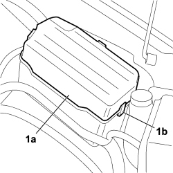
1. Undo the fixing nut (1a) for the electrical connection (1b), positive lead, to junction unit (1c), and disconnect the connection.
| Description | Connector | |
|---|---|---|
| 1b | MAXI FUSE BOX ON BATTERY | See B099 MAXI FUSE BOX ON BATTERY |
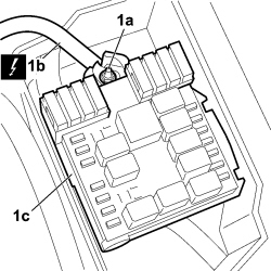
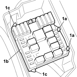
1. Prise up the two clips (1a) retaining junction unit (1b), turn forward toward the engine and prise out of the retainers on pivot pins (1c).
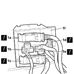
1. Release from the anchorages and disconnect electrical connections (1a) (1b) (1c) (1d) and (1e), on the underside of control unit (1f) and remove the junction unit from the vehicle.
| Description | Connector | |
|---|---|---|
| 1a | ENGINE COMPARTMENT JUNCTION UNIT | See B001 ENGINE COMPARTMENT JUNCTION UNIT |
| Description | Connector | |
|---|---|---|
| 1b | ENGINE COMPARTMENT JUNCTION UNIT | See B001 ENGINE COMPARTMENT JUNCTION UNIT |
| Description | Connector | |
|---|---|---|
| 1c | ENGINE COMPARTMENT JUNCTION UNIT | See B001 ENGINE COMPARTMENT JUNCTION UNIT |
| Description | Connector | |
|---|---|---|
| 1d | ENGINE COMPARTMENT JUNCTION UNIT | See B001 ENGINE COMPARTMENT JUNCTION UNIT |
| Description | Connector | |
|---|---|---|
| 1e | ENGINE COMPARTMENT JUNCTION UNIT | See B001 ENGINE COMPARTMENT JUNCTION UNIT |
1. Release from the anchorage and disconnect electrical connection (1a) of the junction connector,disconnect and relase wiring harness (1c) from anchorage (1b).
| Description | Connector | |
|---|---|---|
| 1a | FRONT/ENGINE COUPLING | See D004 FRONT/ENGINE COUPLING |
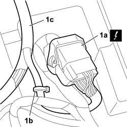
1. Remove both bulkhead couplings (1a) and release wiring harness (1b) from the control unit casing.
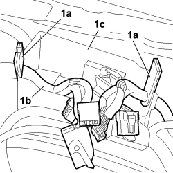
1. Undo nut (1a) securing the control unt casing (1b), disconnect and release anchorage (1c) of the wiring harness, remove the casing from the vehicle.
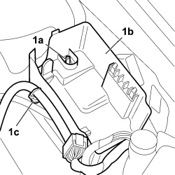
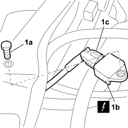
1. Unscrew bolt (1a) securing airbag sensor (1b), disconnect the sensor from the front tray, release from the anchorage and disconnect the airbag sensor electrical connection (1c).
| Description | Connector | |
|---|---|---|
| 1c | SENSOR FOR PASSENGER SIDE FRONT AIRBAG | See K175 DRIVER'S SIDE FRONT AIR BAG SENSOR |
Right
Op. 4450B02 LEFT FRONT WHEEL - R.R
Right
Op. 7055B90 LEFT FRONT WHEEL ARCH LINER - R.R.
Working on the left side (driver side), disconnect the following connections:
| Description | Connector | |
|---|---|---|
| LEFT SIDE DIRECTION INDICATOR | See F020 LEFT SIDE DIRECTION INDICATOR |
| Description | Connector | |
|---|---|---|
| LEFT BRAKE PAD WEAR SENSOR (SWITCH) | See K020 LEFT BRAKE PAD WEAR SENSOR (SWITCH) |
| Description | Connector | |
|---|---|---|
| LEFT FRONT WHEEL SENSOR FOR ABS | See K070 LEFT FRONT WHEEL SENSOR FOR ABS |
| Description | Connector | |
|---|---|---|
| WINDSCREEN/REARSCREEN ELECTRIC WASHER PUMP MOTOR | See N022 WINDSCREEN WASHER/ REAR WINDOW WASHER PUMP MOTOR |
| Description | Connector | |
|---|---|---|
| HEADLAMP WASHER ELECTRIC PUMP MOTOR | See N025 HEADLAMP WASHER PUMP MOTOR |
| Description | Connector | |
|---|---|---|
| LEFT FOG LIGHT | See F015 LEFT FOG LIGHT |
| Description | Connector | |
|---|---|---|
| FRONT HEADLAMP ALIGNMENT CORRECTER POTENTIOMETER (CAF) | See K001 HEADLAMP ALIGNMENT CORRECTOR FRONT POTENTIOMETER (CAF) |
| Description | Connector | |
|---|---|---|
| HEADLAMP ALIGNMENT CONTROL UNIT (CAF) | See M073 HEADLAMP ALIGNMENT CONTROL UNIT (CAF) |
| Description | Connector | |
|---|---|---|
| LEFT HEADLAMP | See F010 LEFT HEADLAMP |
| Description | Connector | |
|---|---|---|
| TYRE PRESSURE CHECK CONTROL UNIT AERIAL | See P012 TYRE PRESSURE CONTROL UNIT ANTENNA |
| Description | Connector | |
|---|---|---|
| BRAKE FLUID LEVEL SENSOR (SWITCH) | See K025 BRAKE FLUID LEVEL SENSOR (SWITCH) |
| Description | Connector | |
|---|---|---|
| ABS FRONT EARTH | See C012 ABS FRONT EARTH |
| Description | Connector | |
|---|---|---|
| BRAKE SYSTEM CONTROL UNIT (NFR) | See M051 BRAKING SYSTEM CONTROL UNIT (NFR) |
| Description | Connector | |
|---|---|---|
| SINGLE-TONE HORN | See P005 |
Op. 7210E22 R.R. WINDSCREEN BASE TRIM
| Description | Connector | |
|---|---|---|
| WINDSCREEN WIPER MOTOR | See N015 |
1. Disconnect both two-pin connectors of the windscreen washer nozzle demister coils.
| Description | Connector | |
|---|---|---|
| 1 | RIGHT WINDSCREEN WASHER (NOZZLE) DEMISTER COIL | See O051 RIGHT WINDSCREEN WASHER (NOZZLE) DEFROZING RESISTANCE |
| Description | Connector | |
|---|---|---|
| 1 | LEFT WINDSCREEN WASHER (NOZZLE) DEMISTER COIL | See O050 LEFT WINDSCREEN WASHER (NOZZLE) DEFROZING RESISTANCE |
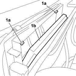
1. Release the retaining clips (1a) and extract the pollen filter (1b).
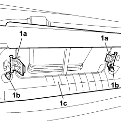
1. Releaase the two retaining clips (1a) for the pollen filter duct, undo the two nuts (1b) fixing the pollen filter duct and remove the duct (1c) from the vehicle.
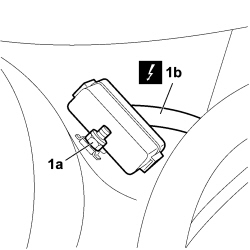
1. Undo the nut (1a) on the earth connection and disconnect the earth lead (1b).
| Description | Connector | |
|---|---|---|
| 1b | LEFT FRONT EARTH | See C010 LEFT FRONT EARTH |
| Description | Connector | |
|---|---|---|
| 1b | RIGHT FRONT EARTH | See C011 RIGHT FRONT EARTH |
- Disconnect the following connections on the right side (passenger side) of the vehicle.
| Description | Connector | |
|---|---|---|
| RIGHT SIDE DIRECTION INDICATOR | See F021 RIGHT SIDE DIRECTION INDICATOR |
| Description | Connector | |
|---|---|---|
| RIGHT FRONT WHEEL SENSOR FOR ABS | See K071 RIGHT FRONT WHEEL SENSOR FOR ABS |
| Description | Connector | |
|---|---|---|
| RIGHT FOG LIGHT | See F016 RIGHT FOG LIGHT |
| Description | Connector | |
|---|---|---|
| RIGHT HEADLAMP | See F011 RIGHT HEADLAMP |
| Description | Connector | |
|---|---|---|
| SENSOR FOR PASSENGER SIDE FRONT AIRBAG | See K176 PASSENGER SIDE FRONT AIR BAG SENSOR |
| Description | Connector | |
|---|---|---|
| BONNET OPENING SWITCH | See I010 BONNET RELEASE SWITCH |
| Description | Connector | |
|---|---|---|
| TYRE PRESSURE CHECK CONTROL UNIT AERIAL | See P012 TYRE PRESSURE CONTROL UNIT ANTENNA |
| Description | Connector | |
|---|---|---|
| EXHAUST GAS SENSOR | See K064 EXHAUST GAS PRESENCE SENSOR |
| Description | Connector | |
|---|---|---|
| ALARM SIREN | See P090 ALARM SIREN |
Op. 7040A44 LEFT DASHBOARD SIDE TRIM - R.R.
Op. 7040A24 LOWER FACIA COVER TRIM - R+R
Op. 5505A35 MAIN BODY COMPUTER/JUNCTION UNIT - R.R.
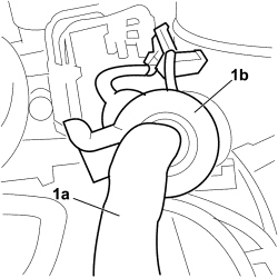
1. Remove integrated wiring (1a) from the engine compartment, prising the bulkhead coupling (1b) out of the body and withdraw carefully from the bulkhead.
Remove the integrated wiring from the vehicle.
Refitting
- Check that the wiring and the pollen filter duct are not damaged.
- Position the wiring on the vehicle and connect:
| Description | Connector | |
|---|---|---|
| RIGHT SIDE DIRECTION INDICATOR | See F021 RIGHT SIDE DIRECTION INDICATOR |
| Description | Connector | |
|---|---|---|
| RIGHT FRONT WHEEL SENSOR FOR ABS | See K071 RIGHT FRONT WHEEL SENSOR FOR ABS |
| Description | Connector | |
|---|---|---|
| RIGHT FOG LIGHT | See F016 RIGHT FOG LIGHT |
| Description | Connector | |
|---|---|---|
| RIGHT HEADLAMP | See F011 RIGHT HEADLAMP |
| Description | Connector | |
|---|---|---|
| SENSOR FOR PASSENGER SIDE FRONT AIRBAG | See K176 PASSENGER SIDE FRONT AIR BAG SENSOR |
| Description | Connector | |
|---|---|---|
| BONNET OPENING SWITCH | See I010 BONNET RELEASE SWITCH |
| Description | Connector | |
|---|---|---|
| TYRE PRESSURE CHECK CONTROL UNIT AERIAL | See P012 TYRE PRESSURE CONTROL UNIT ANTENNA |
| Description | Connector | |
|---|---|---|
| EXHAUST GAS SENSOR | See K064 EXHAUST GAS PRESENCE SENSOR |
| Description | Connector | |
|---|---|---|
| ALARM SIREN | See P090 ALARM SIREN |
| Description | Connector | |
|---|---|---|
| LEFT FRONT EARTH | See C010 LEFT FRONT EARTH |
| Description | Connector | |
|---|---|---|
| RIGHT FRONT EARTH | See C011 RIGHT FRONT EARTH |
| Description | Connector | |
|---|---|---|
| LEFT WINDSCREEN WASHER (NOZZLE) DEMISTER COIL | See O050 LEFT WINDSCREEN WASHER (NOZZLE) DEFROZING RESISTANCE |
| Description | Connector | |
|---|---|---|
RIGHT WINDSCREEN WASHER (NOZZLE) DEMISTER COIL | See O051 RIGHT WINDSCREEN WASHER (NOZZLE) DEFROZING RESISTANCE |
| Description | Connector | |
|---|---|---|
| WINDSCREEN WIPER MOTOR | See N015 WINDSCREEN WIPER MOTOR |
| Description | Connector | |
|---|---|---|
| LEFT SIDE DIRECTION INDICATOR | See F020 LEFT SIDE DIRECTION INDICATOR |
| Description | Connector | |
|---|---|---|
| LEFT BRAKE PAD WEAR SENSOR (SWITCH) | See K020 LEFT BRAKE PAD WEAR SENSOR (SWITCH) |
| Description | Connector | |
|---|---|---|
| LEFT FRONT WHEEL SENSOR FOR ABS | See K070 LEFT FRONT WHEEL SENSOR FOR ABS |
| Description | Connector | |
|---|---|---|
| WINDSCREEN/REARSCREEN ELECTRIC WASHER PUMP MOTOR | See N022 WINDSCREEN WASHER/ REAR WINDOW WASHER PUMP MOTOR |
| Description | Connector | |
|---|---|---|
| HEADLAMP WASHER ELECTRIC PUMP MOTOR | See N025 HEADLAMP WASHER PUMP MOTOR |
| Description | Connector | |
|---|---|---|
| LEFT FOG LIGHT | See F015 LEFT FOG LIGHT |
| Description | Connector | |
|---|---|---|
| FRONT HEADLAMP ALIGNMENT CORRECTER POTENTIOMETER (CAF) | See K001 HEADLAMP ALIGNMENT CORRECTOR FRONT POTENTIOMETER (CAF) |
| Description | Connector | |
|---|---|---|
| HEADLAMP ALIGNMENT CONTROL UNIT (CAF) | See M073 HEADLAMP ALIGNMENT CONTROL UNIT (CAF) |
| Description | Connector | |
|---|---|---|
| LEFT HEADLAMP | See F010 LEFT HEADLAMP |
| Description | Connector | |
|---|---|---|
| TYRE PRESSURE CHECK CONTROL UNIT AERIAL | See P012 TYRE PRESSURE CONTROL UNIT ANTENNA |
| Description | Connector | |
|---|---|---|
| BRAKE FLUID LEVEL SENSOR (SWITCH) | See K025 BRAKE FLUID LEVEL SENSOR (SWITCH) |
| Description | Connector | |
|---|---|---|
| ABS FRONT EARTH | See C012 ABS FRONT EARTH |
| Description | Connector | |
|---|---|---|
| BRAKE SYSTEM CONTROL UNIT (NFR) | See M051 BRAKING SYSTEM CONTROL UNIT (NFR) |
| Description | Connector | |
|---|---|---|
| SINGLE-TONE HORN | See P005 SINGLE TONE HORN |
| Description | Connector | |
|---|---|---|
| SENSOR FOR PASSENGER SIDE FRONT AIRBAG | See K175 DRIVER'S SIDE FRONT AIR BAG SENSOR |
| Description | Connector | |
|---|---|---|
| FRONT/ENGINE COUPLING | See D004 FRONT/ENGINE COUPLING |
| Description | Connector | |
|---|---|---|
| ENGINE COMPARTMENT JUNCTION UNIT | See B001 ENGINE COMPARTMENT JUNCTION UNIT |
| Description | Connector | |
|---|---|---|
| ENGINE COMPARTMENT JUNCTION UNIT | See B001 ENGINE COMPARTMENT JUNCTION UNIT |
| Description | Connector | |
|---|---|---|
| ENGINE COMPARTMENT JUNCTION UNIT | See B001 ENGINE COMPARTMENT JUNCTION UNIT |
| Description | Connector | |
|---|---|---|
| ENGINE COMPARTMENT JUNCTION UNIT | See B001 ENGINE COMPARTMENT JUNCTION UNIT |
| Description | Connector | |
|---|---|---|
| ENGINE COMPARTMENT JUNCTION UNIT | See B001 ENGINE COMPARTMENT JUNCTION UNIT |
| Description | Connector | |
|---|---|---|
| MAXIFUSE BOX ON BATTERY | See B099 MAXIFUSE BOX ON BATTERY |
| Description | Connector | |
|---|---|---|
| MAXIFUSE BOX ON BATTERY | See B099 MAXIFUSE BOX ON BATTERY |
- Position the pollen filter duct on the vehicle and secure.
Op. 5505A35 MAIN BODY COMPUTER/JUNCTION UNIT - R.R.
Op. 7040A24 LOWER FACIA COVER TRIM - R+R
Op. 7040A44 LEFT DASHBOARD SIDE TRIM - R.R.
Op. 7210E22 R.R. WINDSCREEN BASE TRIM
Op. 7040A44 LEFT DASHBOARD SIDE TRIM - R.R.
Op. 5530B52 BATTERY SUPPORT/DRIP TRAY - R.R
Op. 7055B90 LEFT FRONT WHEEL ARCH LINER - R.R.
Op. 4450B02 LEFT FRONT WHEEL - R.R
- Reconnect the negative battery terminal.
| Description | Connector | |
|---|---|---|
| BATTERY | See A001 BATTERY |
Removing
Op. 5530B52 BATTERY SUPPORT/DRIP TRAY - R.R
1. Unscrew nuts (1a) and disconnect electrical connection (1b) from the battery positive terminal.
| Description | Connector | |
|---|---|---|
| 1b | MAXIFUSE BOX ON BATTERY | See B099 MAXIFUSE BOX ON BATTERY |
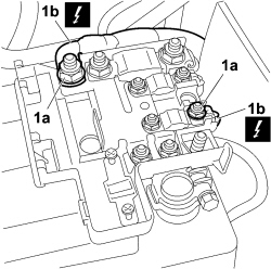
1. Unscrew nuts (1a) and disconnect electrical connection (1b) from the battery negative terminal.
| Description | Connector | |
|---|---|---|
| 1b | BATTERY | See A001 BATTERY |
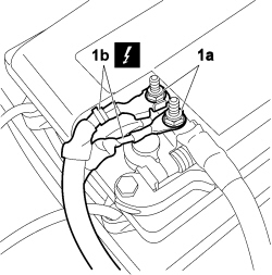
1. Open protective cover (1a) of the MaxiFuse box by undoing the anchorage clip (1b).
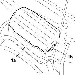
1. Partly remove the MaxiFuse control unit from its housing.
2. Disconnect the electrical connection.
| Description | Connector | |
|---|---|---|
| 2 | ENGINE COMPARTMENT JUNCTION UNIT | See B001 ENGINE COMPARTMENT JUNCTION UNIT |
3. Disconnect the electrical connection.
| Description | Connector | |
|---|---|---|
| 3 | ENGINE COMPARTMENT JUNCTION UNIT | See B001 ENGINE COMPARTMENT JUNCTION UNIT |
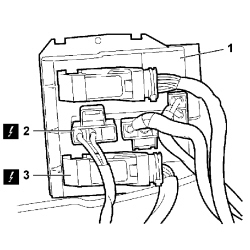
- Release the wiring from the retaining springs.
1. Release the connection, operate safety lever (1a) and disconnect electrical connection (1b).
| Description | Connector | |
|---|---|---|
| 1b | FRONT/ENGINE COUPLING | See D004 FRONT/ENGINE COUPLING |
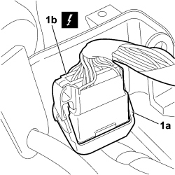
1. Undo the fixing nut (1a) and disconnect the earth lead (1b).
| Description | Connector | |
|---|---|---|
| 1b | LEFT FRONT EARTH | See C010 LEFT FRONT EARTH |
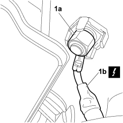
1. Disconnect the electrical connection from the radiator cooling fan.
| Description | Connector | |
|---|---|---|
| 1 | ENGINE FAN MOTOR | See N011 ELECTRIC FAN MOTOR |
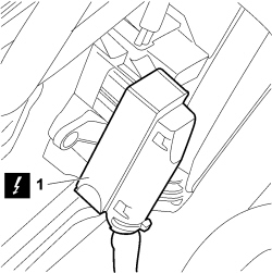
1. Disconnect the electrical connection for the reversing light switch.
| Description | Connector | |
|---|---|---|
| 1 | REVERSING LIGHTS SWITCH | See I020 REVERSING LIGHTS SWITCH |
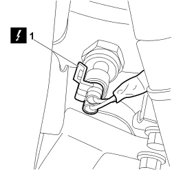
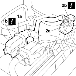
1. Operate safety lever (1a) and disconnect the electrical connection (1b).
| Description | Connector | |
|---|---|---|
| 1b | ENGINE MANAGEMENT CONTROL UNIT | See M010 ENGINE MANAGEMENT ECU |
2. Operate safety lever (2a) and disconnect the electrical connection (2b).
| Description | Connector | |
|---|---|---|
| 2b | ENGINE CABLE/ENGINE SERVICE CABLE COUPLING | See D029 ENGINE CABLES/ENGINE SERVICES CABLE COUPLING |
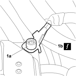
1. Undo the fixing nut (1a) and disconnect the earth lead (1b).
| Description | Connector | |
|---|---|---|
| 1b | EARTH ON ENGINE | See C040 EARTH ON ENGINE |
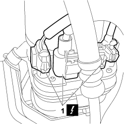
1. Disconnect the electrical connections.
| Description | Connector | |
|---|---|---|
| 1 | ELECTRICAL GUIDE CONTROL UNIT | See M086 ELECTRIC STEERING CONTROL UNIT |
1. Undo the fixing nuts (1a) and disconnect the electrical connections (1b).
| Description | Connector | |
|---|---|---|
| 1b | ALTERNATOR | See A10 ALTERNATOR |
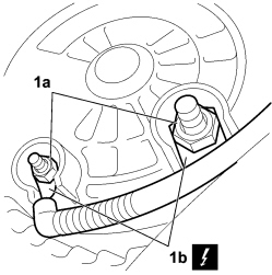
1. Undo the fixing nut (1a) and disconnect the electrical connection (1b).
| Description | Connector | |
|---|---|---|
| 1b | STARTER MOTOR | See A20 STARTER MOTOR |
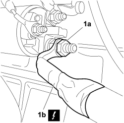
- Remove the engine compartment wiring.
Refitting
- Position the engine compartment wiring on the vehicle.
- Connect the electrical connection and tighten the nut.
| Description | Connector | |
|---|---|---|
| STARTER MOTOR | See A20 STARTER MOTOR |
- Connect the electrical connections and tighten the nuts.
| Description | Connector | |
|---|---|---|
| ALTERNATOR | See A10 ALTERNATOR |
- Connect the electrical connections.
| Description | Connector | |
|---|---|---|
| ELECTRICAL GUIDE CONTROL UNIT | See M086 ELECTRIC STEERING CONTROL UNIT |
- Connect the earth lead and tighten the nut.
| Description | Connector | |
|---|---|---|
| EARTH ON ENGINE | See C040 EARTH ON ENGINE |
- Connect the electrical connection and secure it using the safety lever.
| Description | Connector | |
|---|---|---|
| ENGINE MANAGEMENT CONTROL UNIT | See M010 ENGINE MANAGEMENT ECU |
- Connect the electrical connection and secure it using the safety lever.
| Description | Connector | |
|---|---|---|
| ENGINE CABLE/ENGINE SERVICE CABLE COUPLING | See D029 ENGINE CABLES/ENGINE SERVICES CABLE COUPLING |
- Connect the electrical connection for the reversing light switch.
| Description | Connector | |
|---|---|---|
| REVERSING LIGHTS SWITCH | See I020 REVERSING LIGHTS SWITCH |
- Connect the electrical connection of the radiator cooling fan.
| Description | Connector | |
|---|---|---|
| ENGINE FAN MOTOR | See N011 ELECTRIC FAN MOTOR |
- Connect the earth lead and tighten the nut.
| Description | Connector | |
|---|---|---|
| LEFT FRONT EARTH | See C010 LEFT FRONT EARTH |
- Connect the electrical connection, secure with the safety lever and fasten to the safety clip.
| Description | Connector | |
|---|---|---|
| FRONT/ENGINE COUPLING | See D004 FRONT/ENGINE COUPLING |
- Secure the wiring to the anchorage clips.
- Connect the electrical connection.
| Description | Connector | |
|---|---|---|
| ENGINE COMPARTMENT JUNCTION UNIT | See B001 ENGINE COMPARTMENT JUNCTION UNIT |
- Connect the electrical connection.
| Description | Connector | |
|---|---|---|
| ENGINE COMPARTMENT JUNCTION UNIT | See B001 ENGINE COMPARTMENT JUNCTION UNIT |
- Position the MaxiFuse box in its housing.
- Fit the MaxiFuse box protective cover.
- Connect the electrical connections to the battery negative terminal and tighten the nuts.
| Description | Connector | |
|---|---|---|
| BATTERY | See A001 BATTERY |
- Connect the electrical connections to the battery positive terminal and tighten the nuts.
| Description | Connector | |
|---|---|---|
| MAXIFUSE BOX ON BATTERY | See B099 MAXIFUSE BOX ON BATTERY |
Parts & tools for this job For 2005 Fiat Croma
- TOOLDigital multimeterSearch: automotive digital multimeter
- PARTAssorted fuse kitSearch: car fuse assortment kit
- TOOLWire crimper and connector kitSearch: wire crimper connector kit
Links open Amazon search results in a new tab. As an Amazon Associate I earn from qualifying purchases.