
Fuel delivery manifold - r r
- Make
- Fiat
- Model
- Ducato Factory Service Manual
- Year
- 2002–2006
- Section
- Diesel injection system › Fuel delivery manifold - r r
FUEL DELIVERY MANIFOLD - R R
Removing
- Position the vehicle on the lift.
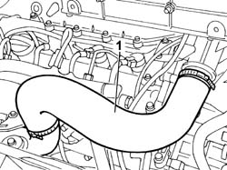
1. Remove the air supply hose to the air/air heat exchanger (intercooler).
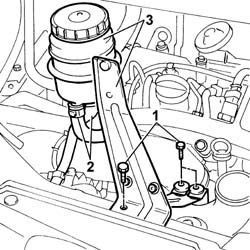
1. Undo the bolts fixing the power assisted steering fluid reservoir mounting bracket.
2. Disconnect the fluid pipes from the reservoir.
3. Remove the power assisted steering fluid reservoir complete with bracket.
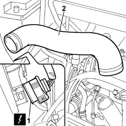
1. Remove the second section of the air supply hose to the air/air heat exchanger (intercooler).
1. Disconnect the electrical connection for the right front light cluster.
| Description | Connector | |
|---|---|---|
| Right headlamp | F011 |
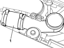
2. Disconnect the bands at the two ends and remove the air pipe from the air/air heat exchager to the intake manifold.
1. Disconnect the electrical connections:
| Description | Connector | |
|---|---|---|
| Injector | N070A |
| Description | Connector | |
|---|---|---|
| Injector | N070B |
| Description | Connector | |
|---|---|---|
| Injector | N070C |
| Description | Connector | |
|---|---|---|
| Injector | N070D |
| Description | Connector | |
|---|---|---|
| Fuel pressure sensor | K083 |
| Description | Connector | |
|---|---|---|
| Air pressure - temperature sensor | K044 |
| Description | Connector | |
|---|---|---|
| Heater plugs | A040A |
| Description | Connector | |
|---|---|---|
| Heater plugs | A040B |
| Description | Connector | |
|---|---|---|
| Heater plugs | A040C |
| Description | Connector | |
|---|---|---|
| Heater plugs | A040D |
| Description | Connector | |
|---|---|---|
| Timing sensor | K047 |
| Description | Connector | |
|---|---|---|
| Fuel pressure regulator | N077 |
- Release the wiring from the bands and move it sideways.
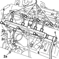
1. Undo the connector for the supply pipe from the pressure pump to the return manifold
2. Undo the fixing bolt (2a), undo the connector (2b) and disconnect the supply pipe (2c) from the pump to the fuel manifold.
3. Undo the connectors for the supply pipes from the manifold to the injectors.
4. Undo the bolts fixing the fuel manifold to the camshaft housing.
5. Remove the fuel manifold complete with supply pipes to the injectors.
Refitting
- Fit the fuel manifold complete with supply pipes to the injectors.
Each time work is carried out on the pipe from the pressure pump to the fuel manifold, it has to be replaced with a new on to prevent fuel leaks from the connectors.
- Tighten the bolts fixing the fuel manifold to torque.
| Value - daNm | Fastening | Component | Ø | |
|---|---|---|---|---|
| 2.5 | Bolt | INJECTOR FUEL MANIFOLD (DIESEL) | M8 |
- Tighten the connectors for the pipes on the injectors to torque.
| Value - daNm | Fastening | Component | Ø | |
|---|---|---|---|---|
| 2.3 | Connectors | INJECTOR FUEL MANIFOLD PIPE | M12X1.5 |
- Tighten the connector for the fuel supply pipe from the pressure pump to torque.
| Value - daNm | Fastening | Component | Ø | |
|---|---|---|---|---|
| 2.3 | Connector | PRESSURE PUMP LINE TO FUEL MANIFOLD | M14 |
- Tighten the bolt fixing the fuel supply pipe from the pressure pump to the bracket.
- Screw in the connector for the return pipe from the single fuel manifold to the return manifold and tighten it to torque.
| Value - daNm | Fastening | Component | Ø | |
|---|---|---|---|---|
| 4 | Connector | INJECTOR FUEL MANIFOLD (DIESEL) | M16 |
- Tighten the bolts fixing the power assisted steering fluid reservoir mounting bracket.
- Fit the air supply hose to the air/air heat exchanger (intercooler).
- Remove the vehicle from the lift.
- Position the injection wiring and connect the electrical connections disconnected previously.
| Description | Connector | |
|---|---|---|
| Injector | N070A |
| Description | Connector | |
|---|---|---|
| Injector | N070B |
| Description | Connector | |
|---|---|---|
| Injector | N070C |
| Description | Connector | |
|---|---|---|
| Injector | N070D |
| Description | Connector | |
|---|---|---|
| Fuel pressure sensor | K083 |
| Description | Connector | |
|---|---|---|
| Fuel pressure regulator | N077 |
| Description | Connector | |
|---|---|---|
| Heater plugs | A040A |
| Description | Connector | |
|---|---|---|
| Heater plugs | A040B |
| Description | Connector | |
|---|---|---|
| Heater plugs | A040C |
| Description | Connector | |
|---|---|---|
| Heater plugs | A040D |
| Description | Connector | |
|---|---|---|
| Timing sensor | K047 |
| Description | Connector | |
|---|---|---|
| Fuel pressure regulator | N077 |
- Fit the air pipe from the air/air heat exchanger to the intake manifold.
- Connect the electrical connection for the right front light cluster.
| Description | Connector | |
|---|---|---|
| Right headlamp | F011 |
- Fit the second section of the air supply hose to the air/air heat exchanger (intercooler).
- Fit the power assisted steering fluid reservoir complete with bracket.
- Connect the fluid pipes to the reservoir.
- Tighten the bolts fixing the power assisted steering fluid reservoir mounting bracket.
- Fit the air supply hose to the air/air heat exchanger (intercooler).
- Remove the vehicle from the lift.
Removing
See in Op. 1048B22
See in Op. 1048B14
See in Op. 1060F20
See in Op. 1060G28
See in Op. 1060F36
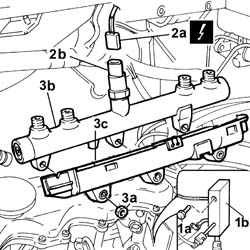
1. Undo the fixing bolt (1a) and move the fuel return manifold pipe (1b) aside.
2. Disconnect the electrical connection (2a) for the fuel pressure sensor (2b).
| Description | Connector | |
|---|---|---|
| 2a | Fuel pressure sensor | K083 |
3. Undo the fixing nuts (3a) and move the brackets on the fastenings aside and remove the single fuel manifold pipe (3b) wih the protective casing (3c).
Refitting
- Place the single fuel manifold pipe and protection in position.
- Position the brackets on the fastenings.
- Tighten the fixing nuts.
- Connect the electrical connection for the fuel pressure sensor.
| Description | Connector | |
|---|---|---|
| Fuel pressure sensor | K083 |
- Position the fuel return manifold pipe and tighten the fixing bolt.
See in Op. 1060F36
See in Op. 1060G28
See in Op. 1060F20
See in Op. 1048B14
See in Op. 1048B22
Removing
See in Op. 1060F20
See in Op. 1060F36
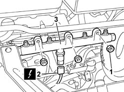
1. Undo the nuts fixing the fuel manifold to the cylinder head.
2. Disconnect the electrical connection for the fuel pressure sensor.
| Description | Connector | |
|---|---|---|
| 2 | Fuel pressure sensor | K083 |
3. Remove the single fuel manifold.
Refitting
- Position the single fuel manifold in the special housing on the intake manifold.
Each time work is carried out on the pipes between the manifold and the injectors, they have to be replaced with new ones to prevent fuel leaks from the connectors.
- Tighten the nuts fixing the fuel manifold to torque.
| Value - daNm | Fastening | Component | Ø | |
|---|---|---|---|---|
| 2,3 | Nut | INJECTOR FUEL MANIFOLD (DIESEL) |
- Connect the electrical connection for the fuel pressure sensor.
| Description | Connector | |
|---|---|---|
| Fuel pressure sensor | K083 |
See in Op. 1060F36
See in Op. 1060F20
Parts & tools for this job For 2002 Fiat Ducato
- PARTFuel filterSearch: Fiat Ducato 2002 fuel filter
- TOOLFuel pressure test kitSearch: fuel pressure test kit
- TOOLFuel line disconnect toolSearch: fuel line disconnect tool
Links open Amazon search results in a new tab. As an Amazon Associate I earn from qualifying purchases.