
Engine oil pump, removed - check at bench
- Make
- Fiat
- Model
- Stilo Factory Service Manual
- Year
- 2001–2007
- Section
- Engine lubrication system › Engine oil pump, removed - check at bench
Engine oil pump, removed - check at bench
Dismantling
1. Undo the bolts (1a) and remove the intake duct (1b).
2. Remove the gasket.
3. Undo the bolts (3a) and remove the oil pump cover (3b).
Use a percussion screwdriver to undo the abovementioned bolts.
4. Remove the driven gear.
5. Remove the drive gear.
6. Undo the catch (6a) and remove the oil pressure relief valve (6b).
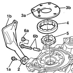
Dismantling
1. Undo the bolts (1a) and remove the intake duct (1b).
2. Remove the gasket
3. Undo the bolts (3a) and remove the oil pump cover (3b).
Use a percussion screwdriver to undo the abovementioned bolts.
4. Remove the driven gear.
5. Remove the drive gear.
6. Undo the catch (6a) and remove the oil pressure relief valve (6b).
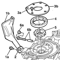
Dismantling
1. Undo the bolts fixing engine oil intake.
2. Remove the engine oil intake.
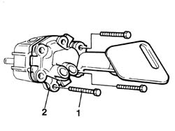
Dismantling
1. Undo the cap (1a) and remove the oil pressure relief valve (1b).
2. Undo the bolts (2a) and remove the oil pump cover (2b).
3. Remove the drive gear.
4. Remove the driven gear.
Remove the crankshaft front oil seal.
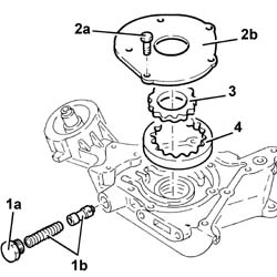
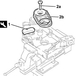
Dismantling
Position the engine oil pump in a vice fitted with projective jaws.
1. Fit the tool.
| Name | Country | |
|---|---|---|
| 1 | Counter-torque/Template | 1.870.799.000 |
2. Undo the left-handed bolt (2a) and remove the oil pump drive chain assembly (2b).
Remove the tool.
| Name | Country | |
|---|---|---|
| Counter-torque/Template | 1.870.799.000 |
Dismantling
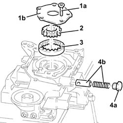
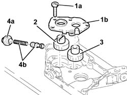
1. Undo the bolts (1a) and remove the oil pump cover (1b).
2. Remove the drive gear.
3. Remove the driven gear.
4. Undo plug (4a) and remove oil pressure relief valve (4b).
Remove the crankshaft front oil seal.
Dismantling
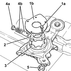
1. Undo the bolts (1a) and remove the oil pump cover (1b).
2. Remove the drive gear.
3. Remove the driven gear.
4. Undo plug (4a) and remove oil pressure relief valve (4b).
5. Remove the crankshaft front oil seal.
1. Remove crankshaft front oil seal with a suitable tool in the special groove
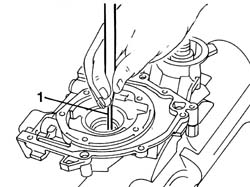
1. Remove crankshaft front oil seal with a suitable tool in the special groove
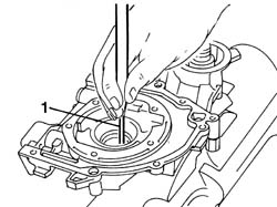
Reassembling
Suitably secure the oil pump.
1. Check that the clearance between the pump casing and the gears is within the recommended values.
| Measurement | Value | ||
|---|---|---|---|
| 1 | Radial clearance between pump casing and gears (mm) | 0.110 - 0.180 |
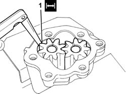
Reassembling
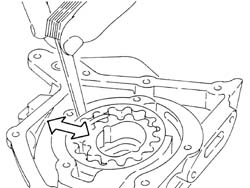
Check that the radial clearance between pump casing and driven gear is within the recommended limits; If not, replace the oil pump assembly
| Measurement | Value | ||
|---|---|---|---|
| Radial clearance between pump casing and driven gear (mm) | 0.080 - 0.186 |
1. Undo the bolts (1a) and remove the oil pump cover (1b).
2. Remove the driven gear.
3. Remove the drive gear.
4. Undo the plug (4a) and remove the oil pressure relief valve (4b).
Remove the crankshaft front oil seal.
Reassembling
Check that the radial clearance between pump casing and driven gear is within the recommended limits; If not, replace the oil pump assembly
| Measurement | Value | ||
|---|---|---|---|
| Radial clearance between pump casing and driven gear (mm) | 0.080 - 0.186 |
Reassembling
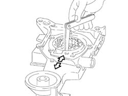
Check that the radial clearance between pump casing and driven gear is within the recommended limits; If not, replace the oil pump assembly
| Measurement | Value | ||
|---|---|---|---|
| Radial clearance between pump casing and driven gear (mm) | 0.080 - 0.186 |
Reassembling
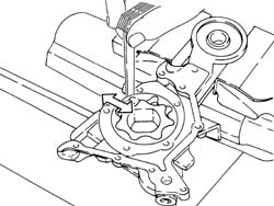
1. Check that the radial clearance between driven gear and pump casing is within the recommended limits
| Measurement | Value | ||
|---|---|---|---|
| 1 | Radial clearance between driven gear and pump casing (mm) | 0.100 - 0.210 |
Reassembling
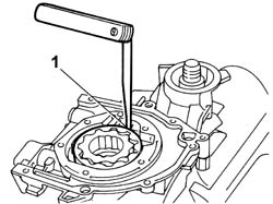
1. Check that the radial clearance between driven gear and pump casing is within the recommended limits
| Measurement | Value | ||
|---|---|---|---|
| 1 | Radial clearance between driven gear and pump casing (mm) | 0.100 - 0.210 |
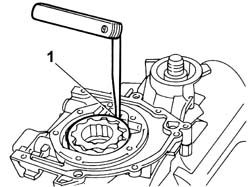
1. Check the end float between the cover support plane and surface of the gears.
| Measurement | Value | ||
|---|---|---|---|
| 1 | End float between pump support plane and gears (mm) | 0.040 - 0.106 |
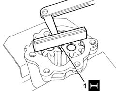
Check that the clearance between the oil pump cover support plane and the upper side of the gears is within the recommended limits; If not, replace the oil pump assembly
| Measurement | Value | ||
|---|---|---|---|
| Clearance between pump cover contact surface and top side of gears (mm) | 0.025 - 0.070 |
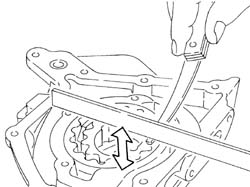
Reassembling
Check the wear of the oil pump drive chain and, if necessary, replace the oil pump drive chain assembly.
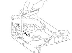
Check that the radial clearance between driven gear and pump casing is within the recommended limits; if this is not the case, replace the engine oil pump.
| Measurement | Value | ||
|---|---|---|---|
| Radial clearance between gears and pump casing (mm) | 0.110 - 0.180 |
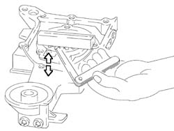
Check that the clearance between the oil pump cover support plane and the upper side of the gears is within the recommended limits; If not, replace the oil pump assembly
| Measurement | Value | ||
|---|---|---|---|
| Clearance between pump cover support surface and top of gears (mm) | 0.025 - 0.070 |
Check that the clearance between the oil pump cover support plane and the upper side of the gears is within the recommended limits; If not, replace the oil pump assembly
| Measurement | Value | ||
|---|---|---|---|
| Clearance between pump cover support surface and top of gears (mm) | 0.025 - 0.070 |
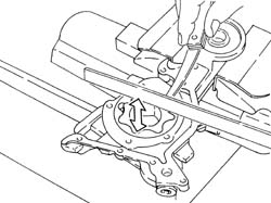
1. Check that the axial clearance between the upper side of the gears and the oil pump cover support plane is within the recommended limits.
| Measurement | Value | ||
|---|---|---|---|
| 1 | End float between upper side of gears and cover support surface (mm) | 0.025 - 0.070 |
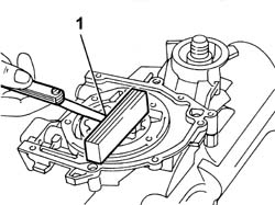
1. Check that the axial clearance between the upper side of the gears and the oil pump cover support plane is within the recommended limits.
| Measurement | Value | ||
|---|---|---|---|
| 1 | End float between upper side of gears and cover support surface (mm) | 0.025 - 0.070 |
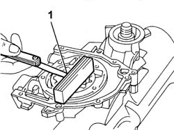
Calculate the clearance between the internal diameter of the driven gear and the pump casing housing bearing.
| Measurement | Value | ||
|---|---|---|---|
| Clearance between driven gear internal diameter and pump casing housing (mm) | 0.015 - 0.048 |
Calculate the clearance between the diameter of the drive gear shaft and the pump casing housing.
| Measurement | Value | ||
|---|---|---|---|
| Clearance between drive gear shaft diameter and pump casing housing (mm) | 0.016 - 0.048 |
Calculate the clearance between the drive gear and the driven gear.
| Measurement | Value | ||
|---|---|---|---|
| Clearance between drive gear and driven gear (mm) | 0.30 |
Using suitable equipment, check the functional characteristics of the relief valve spring.
| Measurement | Value | ||
|---|---|---|---|
| Relief valve spring height (mm) | 22.5 | ||
| Under load (daN) | 6.51 - 6.82 | ||
| Measurement | Value | ||
|---|---|---|---|
| Relief valve spring height (mm) | 21 | ||
| Under load (daN) | 6.92 - 7.21 | ||
If even only one of the checks carried out on the pump casing, the gears or the valve gives a result which is outside of the tolerance range, replace the complete oil pump.
Check that the height of the spring for the engine oil pressure relief valve is within the recommended limits; if this is not the case, replace the spring.
| Measurement | Value | ||
|---|---|---|---|
| Height (mm) | 36 | ||
| Check load (daN) | 6.28 - 7.03 | ||
Fit the driven gear.
Fit the drive gear.
Fit the oil pump cover and tighten the bolts.
Manually rotate the gears to check that they turn without sticking.
Fit the oil pressure relief valve and tighten the cap.
The crankshaft front oil seal should be fitted using the special tool after fitting the front cover to the engine block.
Check that the axial clearance between the upper side of the gears and the oil pump cover support plane is within the recommended limits; if this is not the case, replace the engine oil pump.
| Measurement | Value | ||
|---|---|---|---|
| End float between upper side of gears and pump cover support surface (mm) | 0.016 - 0.086 |
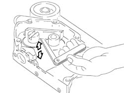
Check that the height of the spring for the engine oil pressure relief valve is within the recommended limits; if this is not the case, replace the spring.
| Measurement | Value | ||
|---|---|---|---|
| Engine oil pressure limiting valve spring height (mm) | 35 | ||
| Check load (daN) | 11.73 - 12.51 | ||
Fit the oil pressure relief valve and tighten the plug.
| Fastening | Component | Ø | Value (daNm) | |
|---|---|---|---|---|
| Plug | OIL PRESSURE LIMITING VALVE | 1,6 - 2,0 |
Fit the driven gear.
Fit the drive gear.
Fit the oil pump cover and tighten the bolts.
| Fastening | Component | Ø | Value (daNm) | |
|---|---|---|---|---|
| Bolt | CRANKSHAFT FRONT COVER | 0.8 - 1.2 |
Manually rotate the gears to check that they turn without sticking.
Check that the height of the spring for the engine oil pressure relief valve is within the recommended limits; if this is not the case, replace the spring.
| Measurement | Value | ||
|---|---|---|---|
| Engine oil pressure limiting valve spring height (mm) | 35 | ||
| at test load (daN) | 11.73 - 12.51 | ||
Fit the oil pressure relief valve in its seat and tighten the cap.
Refit the driven gear.
Refit the drive gear.
Place the engine oil pump cover back in its housing and secure using the bolts.
Manually rotate the gears to check that they turn without sticking.
Check that the height of the spring for the engine oil pressure relief valve is within the recommended limits.
| Measurement | Value | ||
|---|---|---|---|
| Check load (daN) | 11.73 - 12.51 | ||
| Height (mm) | 35 | ||
Fit the oil pressure relief valve and tighten the plug.
Fit the drive gear.
Fit the driven gear.
Fit the oil pump cover and tighten the bolts.
| Fastening | Component | Ø | Value (daNm) | |
|---|---|---|---|---|
| Bolt | COVER | M6 | 0.7 |
Manually rotate the gears to check that they turn without sticking.
Fit the intake duct complete with gasket and fix it to the oil pump using the bolts.
Note: the crankshaft front oil seal must be fitted to the engine oil pump on the crankcase (see op. 1084B14 engine oil pump - r+r with power unit removed ).
Check that the height of the spring for the engine oil pressure relief valve is within the recommended limits.
| Measurement | Value | ||
|---|---|---|---|
| Oil pressure relief valve spring height (mm) | 35 | ||
| Check load (daN) | 11.73 - 12.51 | ||
Fit the oil pressure relief valve and tighten the plug.
Fit the drive gear.
Fit the driven gear.
Fit the oil pump cover and tighten the bolts.
| Fastening | Component | Ø | Value (daNm) | |
|---|---|---|---|---|
| Bolt | COVER | M6 | 0.7 |
Manually rotate the gears to check that they turn without sticking.
Fit the intake duct complete with gasket and fix it to the oil pump using the bolts.
The crankshaft front oil seal must be fitted to the oil pump on the crankcase ( - 1084B14 engine oil pump - r+r with power unit removed ).
Check that the height of the spring for the engine oil pressure relief valve is within the recommended limits; if this is not the case, replace the spring.
| Measurement | Value | ||
|---|---|---|---|
| Engine oil pressure limiter spring free height (mm) | 49,5 | ||
| Check load (daN) | 11.73 - 12.51 | ||
| Measurement | Value | ||
|---|---|---|---|
| Engine oil pressure limiting valve spring height (mm) | 35 | ||
| Check load (daN) | 11.96 - 12.76 | ||
| Measurement | Value | ||
|---|---|---|---|
| Wire or bar diameter (mm) | 1,8 ± 0,15 |
| Measurement | Value | ||
|---|---|---|---|
| Outer diameter (mm) | 11,5 ± 0,10 |
| Measurement | Value | ||
|---|---|---|---|
| Total number of coils (-) | 16 |
Fit the engine oil pressure relief valve and tighten the plug to the specified torque.
| Fastening | Component | Ø | Value (daNm) | |
|---|---|---|---|---|
| Plug | OIL PRESSURE LIMITING VALVE | 1,6 - 2,0 |
Fit the drive gear.
Fit the driven gear.
Fit the oil pump cover and tighten the bolts.
| Fastening | Component | Ø | Value (daNm) | |
|---|---|---|---|---|
| Bolt | OIL PUMP GEAR COVER | 0,8 - 1,2 |
Manually rotate the gears to check that they turn without sticking.
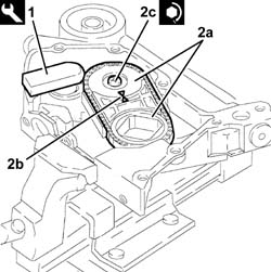
Position the engine oil pump in a vice fitted with projective jaws.
1. Fit the tool.
| Name | Country | |
|---|---|---|
| 1 | Counter-torque/Template | 1.870.799.000 |
2. Fit the oil pump drive chain assembly (2a) so that the references (2b) coincide and tighten the bolt (left) (2c) to torque.
| Fastening | Component | Ø | Value (daNm) | |
|---|---|---|---|---|
| 2c | Left hand thread bolt | OIL PUMP DRIVE CHAIN ASSEMBLY | M10 | 4.5 - 5.5 |
Parts & tools for this job For 2001 Fiat Stilo
- PARTEngine gasket setSearch: Fiat Stilo 2001 engine gasket set
- TOOLTorque wrenchSearch: 3/8 inch torque wrench
- TOOLFeeler gauge setSearch: feeler gauge set
Links open Amazon search results in a new tab. As an Amazon Associate I earn from qualifying purchases.