Wiring diagrams and electrical functions Asr / tcs wiring diagram
ASR / TCS WIRING DIAGRAM
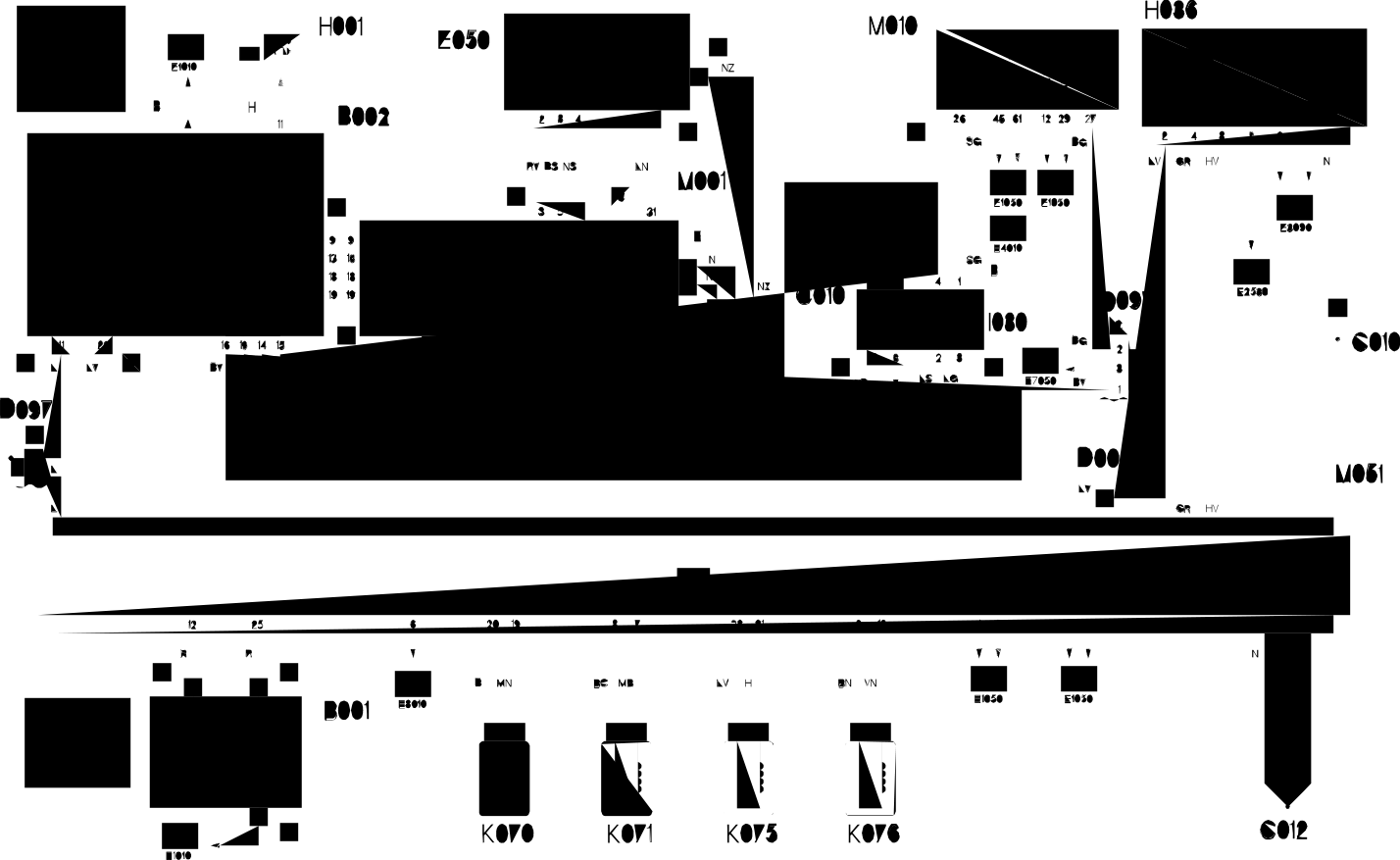
3.0 V6, 3.2 V6 · Automatic Transmission
Wiring Diagram
Components
Component code Name Assembly reference B001 Engine compartment junction unit 5505A B002 Junction unit under dashboard C010 Left front earth C012 C022 Centre dashboard earth D001 D006 Front/rear coupling D097 Short circuit coupling E050 Instrument panel H001 Ignition switch H036 Controls on tunnel I030 Interruttore pedale freno 5520G K070 3340A K071 Right front wheel sensor for ABS K075 Left rear wheel sensor for ABS K076 3340A M001 Body computer M010 Engine management control unit 1056B M051 Braking system control unit (NFR)
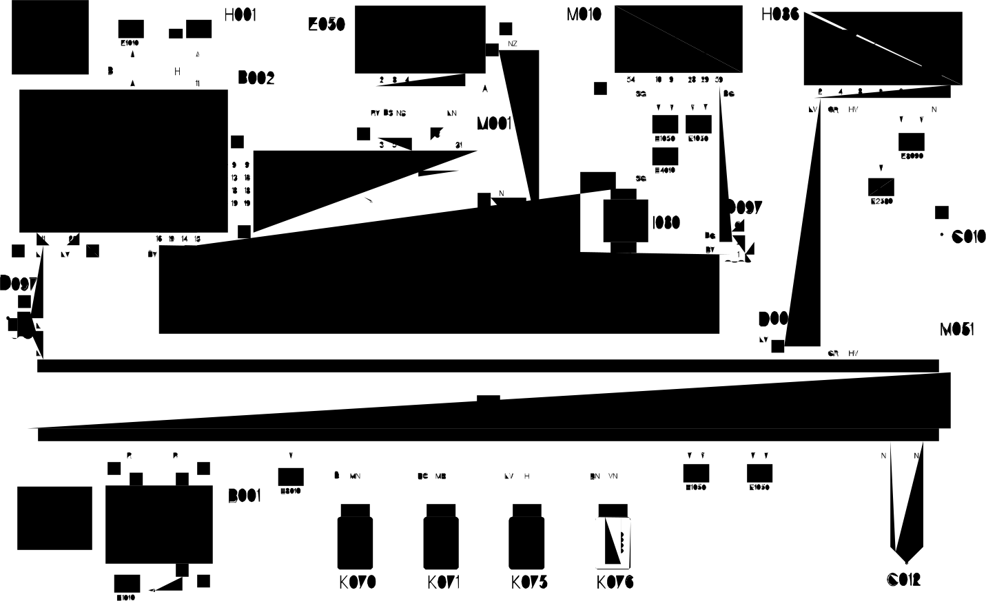
2.4 JTD 10V
Wiring Diagram
Components
Component code Name Assembly reference B001 Engine compartment junction unit 5505A B002 Junction unit under dashboard C010 Left front earth C012 C022 Centre dashboard earth D001 D006 Front/rear coupling D097 Short circuit coupling E050 Instrument panel H001 Ignition switch H036 Controls on tunnel I030 Interruttore pedale freno 5520G K070 3340A K071 Right front wheel sensor for ABS K075 Left rear wheel sensor for ABS K076 3340A M001 Body computer M010 Engine management control unit 1056B M051 Braking system control unit (NFR)
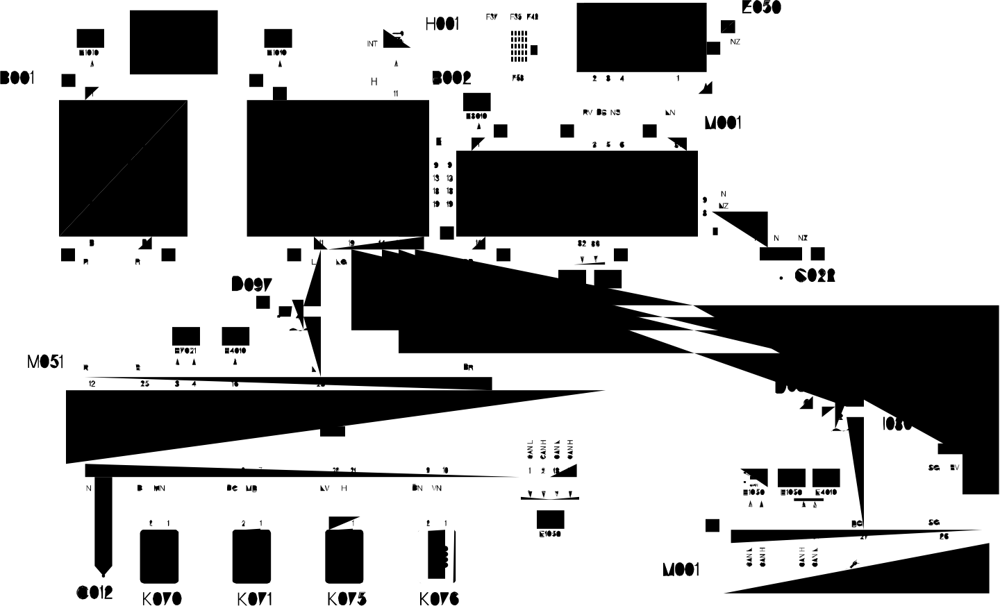
2.0 TB, 2.4 20V
Wiring Diagram
Components
Component code Name Assembly reference B001 Engine compartment junction unit 5505A B002 Junction unit under dashboard C012 C022 Centre dashboard earth D001 D097 Short circuit coupling E050 Instrument panel H001 Ignition switch H036 Controls on tunnel I030 Interruttore pedale freno 5520G K070 3340A K071 Right front wheel sensor for ABS K075 Left rear wheel sensor for ABS K076 3340A M001 Body computer M010 Engine management control unit 1056B M051 Braking system control unit (NFR)
19 Electrical