
Introduction – circuit diagram
- Make
- Land Rover
- Model
- Discovery Electrical Troubleshooting Manual
- Year
- 1995
- Section
- Circuit diagram › Introduction – circuit diagram
INTRODUCTION – CIRCUIT DIAGRAM
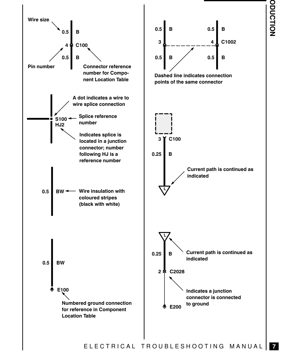
Wire size \ 05] B = 05] 05]
4 | C1002 / 05] 2 C100 B AN 05] 05] Pin number Connector reference number for CompoDashed line indicates connection nent Location Table points of the same connector
A dot indicates a wire to yd wire splice connection Coa) — S100 <— Splice reference HJ2 number AN Indicates splice is b—ed located in a junction 3 J c100 connector; number following HJ is a 025] reference number
Current path is continued as indicated
0.5 | BW =— Wire insulation with coloured stripes (black with white)
0.25 AN Current path is continued as indicated 0.5) BW
2x C2028 2 E100 AN Indicates a junction NN connector is connected Numbered ground connection E200 to ground for reference in Component Location Table
ELECTRICAL TROUBLESHOOTING MANUAL
Oo oO
Parts & tools for this job For 1995 Land Rover Discovery
- TOOLDigital multimeterSearch: automotive digital multimeter
- PARTAssorted fuse kitSearch: car fuse assortment kit
- TOOLWire crimper and connector kitSearch: wire crimper connector kit
Links open Amazon search results in a new tab. As an Amazon Associate I earn from qualifying purchases.