
Introduction – circuit diagram
- Make
- Land Rover
- Model
- Discovery Electrical Troubleshooting Manual
- Year
- 1995
- Section
- Circuit diagram › Introduction – circuit diagram
INTRODUCTION – CIRCUIT DIAGRAM
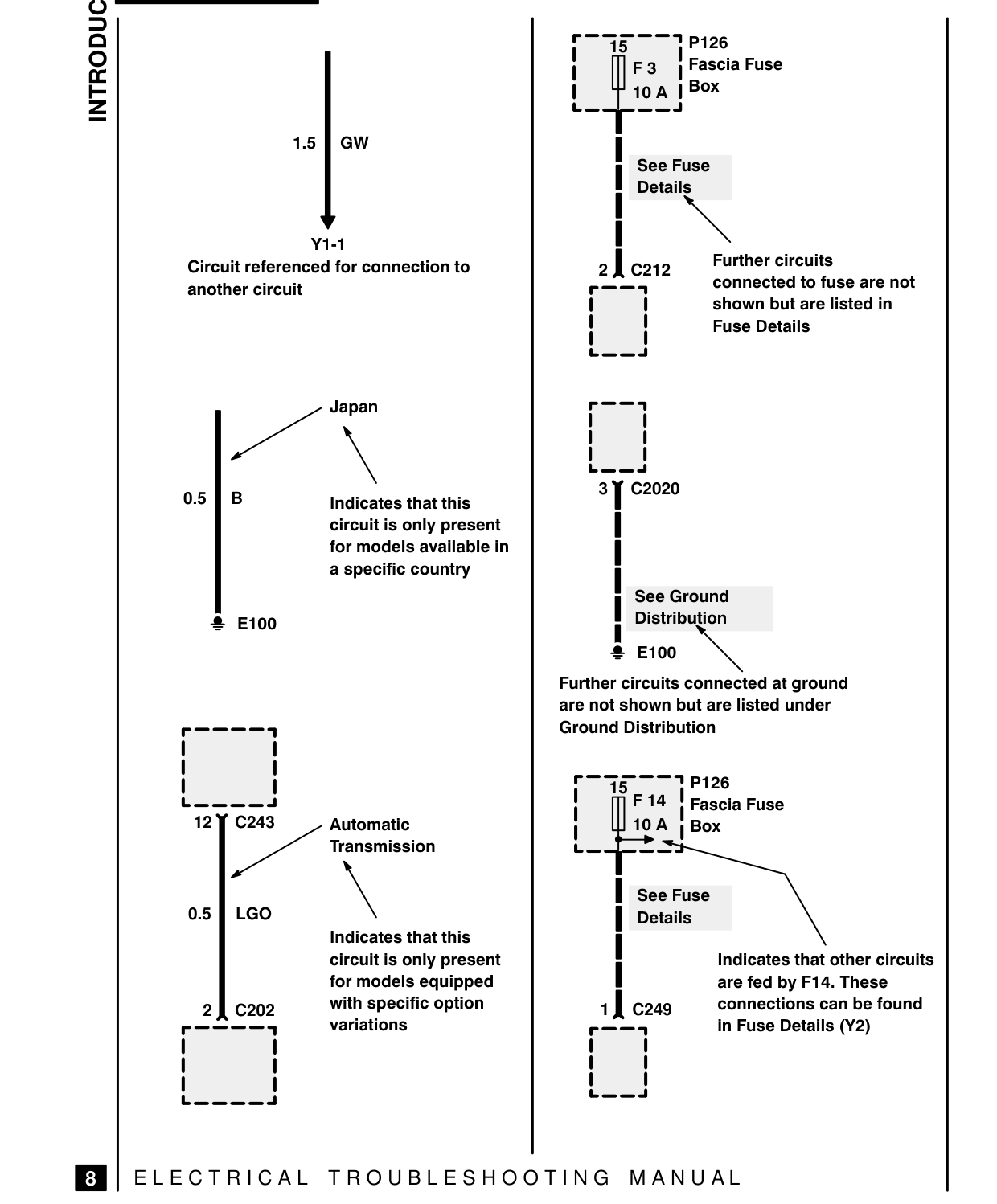
1.5 | GW
Y1-1 Circuit referenced for connection to another circuit
Japan Indicates that this 05] circuit is only present for models available in a specific country 2 E100
12] C243 Automatic _ Transmission 0.5 | LGO Indicates that this
circuit is only present for models equipped 2 1 c202 with specific option variations
EJ | ELECTRICAL TROUBLESHOOTING MANUAL
| 15 P126 F3 | Fascia Fuse 10 A | Box [Hp
See Fuse Details
2 | C212 ruriher cirautts rF——a connected to fuse are no shown but are listed in Fuse Details
fem d
ro he 3Y C2020
I See Ground I Distribution 2 E100 AN Further circuits connected at ground are not shown but are listed under Ground Distribution
r=35 P12 F14 I Fascia Fuse 10A | Box Le | See Fuse Details
Indicates that other circuits are fed by F14. These 1 1 C249 connections can be found r——a in Fuse Details (Y2)
Parts & tools for this job For 1995 Land Rover Discovery
- TOOLDigital multimeterSearch: automotive digital multimeter
- PARTAssorted fuse kitSearch: car fuse assortment kit
- TOOLWire crimper and connector kitSearch: wire crimper connector kit
Links open Amazon search results in a new tab. As an Amazon Associate I earn from qualifying purchases.