
Central locking (Japan) – circuit diagram
- Make
- Land Rover
- Model
- Range Rover Classic Electrical Troubleshooting Manual
- Year
- 1995
- Section
- Circuit diagram › Central locking (Japan) – circuit diagram
Central locking (Japan)Central locking (Japan) – circuit diagram
CENTRAL LOCKING (JAPAN) – CIRCUIT DIAGRAM
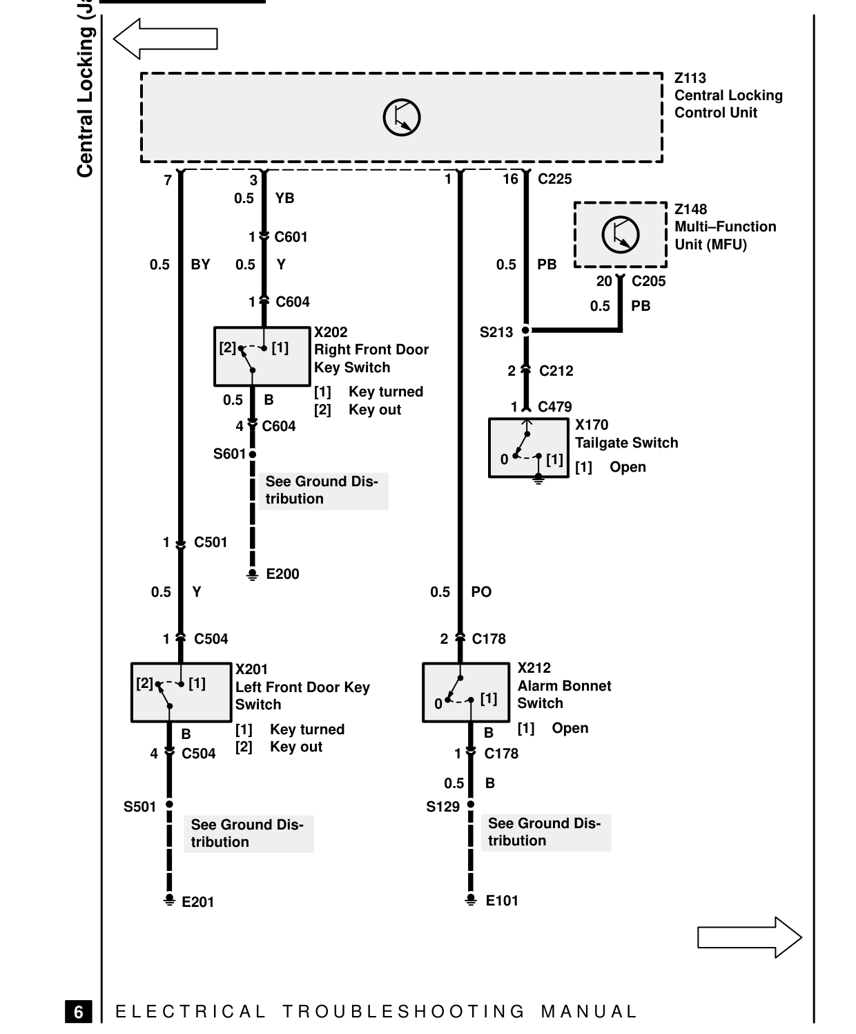
Central Locking (Japan) 7 3 0.5 YB
1 C601 0.5 Y 0.5 BY
1 C604
X202 [2] [1] Right Front Door Key Switch [1] Key turned 0.5 B [2] Key out 4 C604 S601 See Ground Dis- tribution
1 C501
E200 0.5 Y
1 C504
X201 [2] [1] Left Front Door Key Switch [1] Key turned B [2] Key out 4 C504
S501 See Ground Dis- tribution
E201
E L E C T R I C A L T R O U B L E S H O O T I N G
6
Z113 Central Locking Control Unit
1 16 C225
Z148 Multi-Function Unit (MFU) 0.5 PB 20 C205 0.5 PB S213
2 C212
1 C479 X170 Tailgate Switch 0 [1] [1] Open
0.5 PO
2 C178
X212 Alarm Bonnet [1] Switch 0 [1] Open B 1 C178
0.5 B S129 See Ground Dis- tribution
E101
M A N U A L
Parts & tools for this job For 1995 Land Rover Range Rover
- TOOLDigital multimeterSearch: automotive digital multimeter
- PARTAssorted fuse kitSearch: car fuse assortment kit
- TOOLWire crimper and connector kitSearch: wire crimper connector kit
Links open Amazon search results in a new tab. As an Amazon Associate I earn from qualifying purchases.