
Compressor controls – circuit diagram
- Make
- Land Rover
- Model
- Range Rover Classic Electrical Troubleshooting Manual
- Year
- 1995
- Section
- Circuit diagram › Compressor controls – circuit diagram
Compressor controlsCompressor controls – circuit diagram
COMPRESSOR CONTROLS – CIRCUIT DIAGRAM
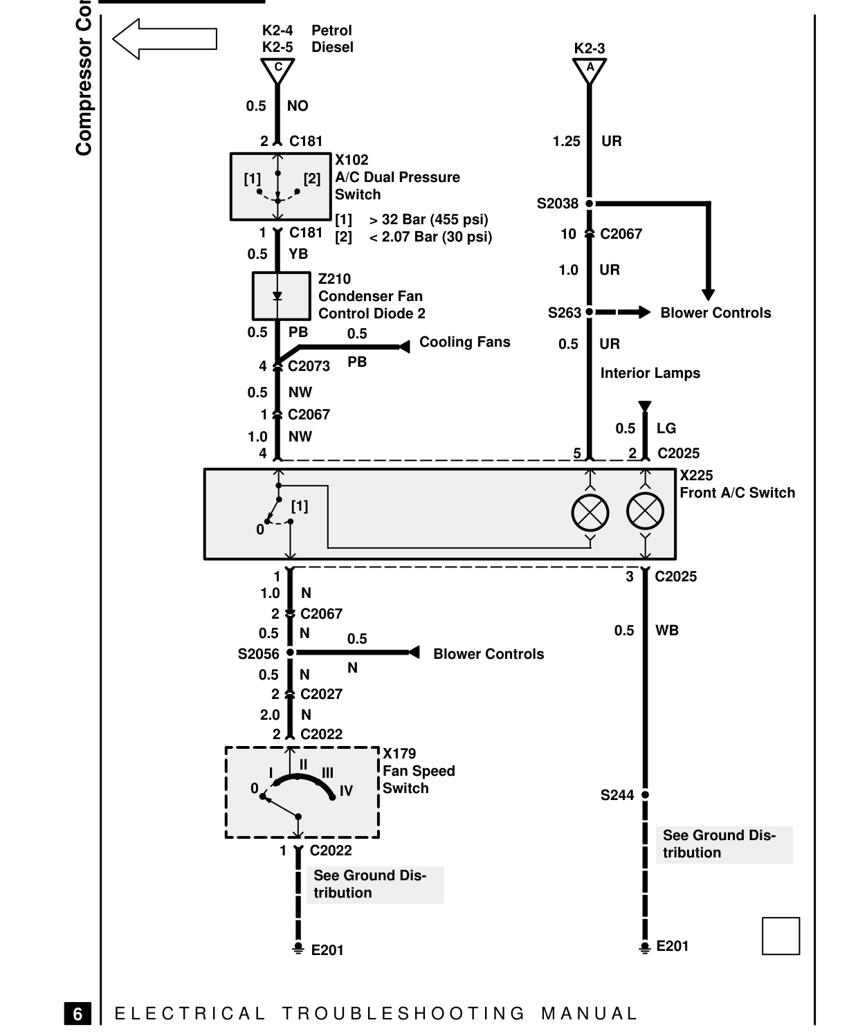
Compressor Controls K2-4 Petrol K2-5 Diesel C
0.5 NO
2 C181 X102 A/C Dual Pressure [1] [2] Switch [1] > 32 Bar (455 psi) 1 C181 [2] < 2.07 Bar (30 psi) 0.5 YB Z210 Condenser Fan Control Diode 2 0.5 PB 0.5
PB 4 C2073 0.5 NW 1 C2067 1.0 NW 4
[1] 0
1 1.0 N 2 C2067 0.5 N 0.5 S2056 N 0.5 N 2 C2027 2.0 N 2 C2022 X179 II Fan Speed I III 0 Switch IV
1 C2022 See Ground Dis- tribution
E201
E L E C T R I C A L T R O U B L E S H O O T I N G
6
K2-3 A
1.25 UR
S2038
10 C2067
1.0 UR
S263 Blower Controls Cooling Fans 0.5 UR
Interior Lamps
0.5 LG 5 2 C2025 X225 Front A/C Switch
3 C2025
0.5 WB Blower Controls
S244
See Ground Dis- tribution
E201
M A N U A L
Parts & tools for this job For 1995 Land Rover Range Rover
- TOOLDigital multimeterSearch: automotive digital multimeter
- PARTAssorted fuse kitSearch: car fuse assortment kit
- TOOLWire crimper and connector kitSearch: wire crimper connector kit
Links open Amazon search results in a new tab. As an Amazon Associate I earn from qualifying purchases.