
Introduction – circuit diagram
- Make
- Land Rover
- Model
- Range Rover Classic Electrical Troubleshooting Manual
- Year
- 1995
- Section
- Circuit diagram › Introduction – circuit diagram
INTRODUCTION – CIRCUIT DIAGRAM
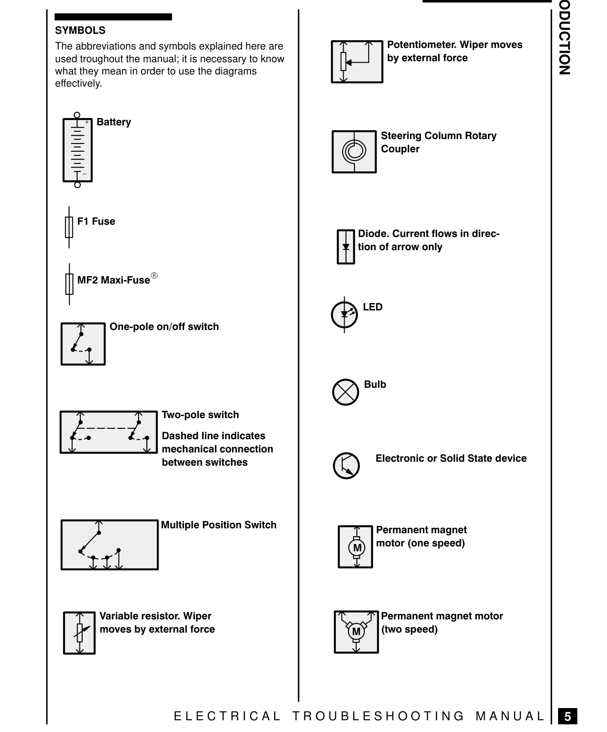
SYMBOLS The abbreviations and symbols explained here are used troughout the manual; it is necessary to know what they mean in order to use the diagrams effectively.
Battery
F1 Fuse
MF2 Maxi-Fuse
A One-pole on/off switch
Peas Two-pole switch Dashed line indicates mechanical connection between switches
Multiple Position Switch
Variable resistor. Wiper by external force moves
ELECTRICAL TROUBLESHOOTING MANUAL | E
oO
Potentiometer. Wiper moves by external force pa
Steering Column Rotary Coupler
Diode. Current flows in direc-
tion of arrow only
LED
X Bulb
Electronic or Solid State device
Permanent magnet motor (one speed)
LL] Permanent magnet motor ko (two speed)
Parts & tools for this job For 1995 Land Rover Range Rover
- TOOLDigital multimeterSearch: automotive digital multimeter
- PARTAssorted fuse kitSearch: car fuse assortment kit
- TOOLWire crimper and connector kitSearch: wire crimper connector kit
Links open Amazon search results in a new tab. As an Amazon Associate I earn from qualifying purchases.