
Introduction – circuit diagram
- Make
- Land Rover
- Model
- Range Rover Classic Electrical Troubleshooting Manual
- Year
- 1995
- Section
- Circuit diagram › Introduction – circuit diagram
INTRODUCTION – CIRCUIT DIAGRAM
Oo
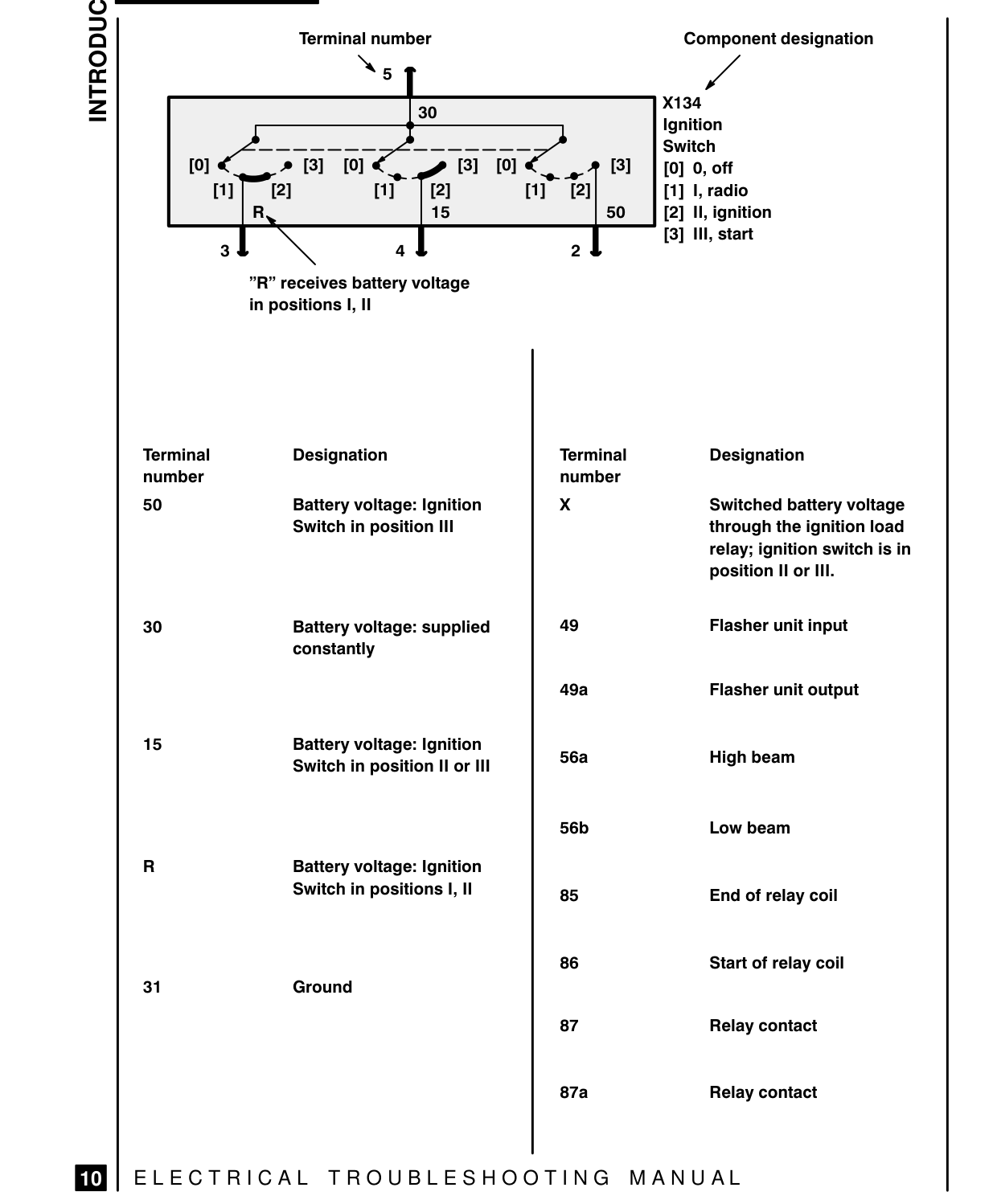
[mn] Terminal number
pd 30
28 01 Lp Bl OIC, nif 15
”R” receives battery voltage in positions |, II
Terminal Designation number
50 Battery voltage: Ignition Switch in position Ill
30 Battery voltage: supplied constantly
15 Battery voltage: Ignition Switch in position II or lil
Battery voltage: Ignition Switch in positions |, I
31 Ground
Bl) | ELECTRICAL TROUBLESHOOTING MANUAL
Component designation
X134 Ignition Switch 2B] |[o]ooff |, radio 50 II, ignition Il, start
Terminal Designation number
Switched battery voltage through the ignition load relay; ignition switch is in position Il or Ill.
49 Flasher unit input
49a Flasher unit output
56a High beam
56b Low beam
85 End of relay coil
86 Start of relay coil
87 Relay contact
87a Relay contact
Parts & tools for this job For 1995 Land Rover Range Rover
- TOOLDigital multimeterSearch: automotive digital multimeter
- PARTAssorted fuse kitSearch: car fuse assortment kit
- TOOLWire crimper and connector kitSearch: wire crimper connector kit
Links open Amazon search results in a new tab. As an Amazon Associate I earn from qualifying purchases.