
Air intake system - VVC
- Make
- MG
- Model
- MGF Factory Workshop Manual
- Year
- 1995–2000
- Section
- Description and operation › Air intake system - VVC
Engine management system - MEMSAir intake system - VVC
AIR INTAKE SYSTEM - VVC
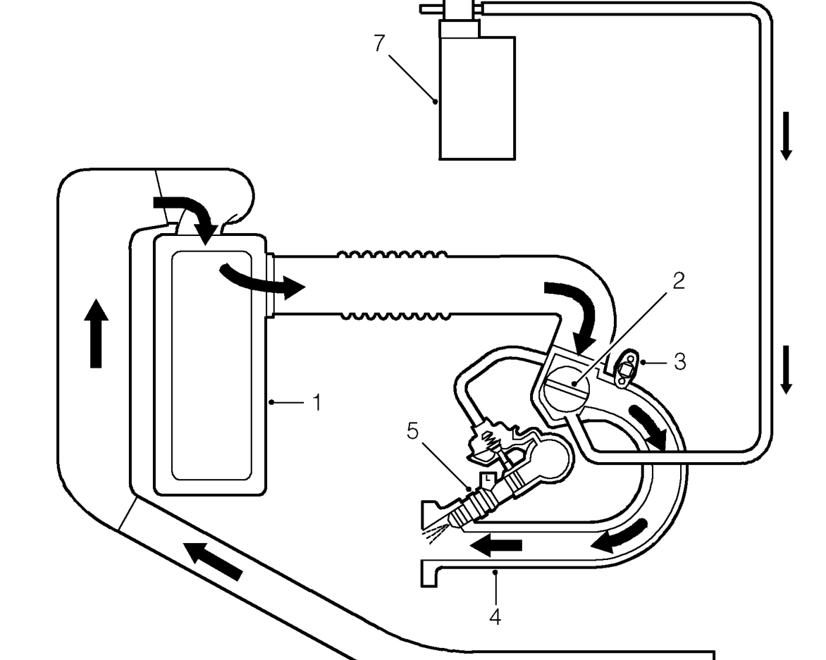
- Air cleaner element
- Throttle disc
- Idle air control valve
- Inlet manifold
Intake air is drawn into the throttle housing through an air filter element. Incorporated in the throttle housing are the throttle disc and the throttle position sensor.
Air passes from the throttle housing via the manifold chamber into the inlet tracts. Fuel is sprayed into the inlet manifold by the injectors and the air/fuel mixture is drawn into the combustion chamber.
- Injector
- Evaporative emission cannister, purge valve
- Evaporative emission cannister
Inlet manifold depression is measured by the MAP sensor which is mounted on the end of the manifold chamber. A signal from the MAP sensor is used by the ECM to calculate the amount of fuel to be delivered by the injectors.
Parts & tools for this job For 1995 MG MGF
- PARTEngine gasket setSearch: MG MGF 1995 engine gasket set
- TOOLTorque wrenchSearch: 3/8 inch torque wrench
- TOOLFeeler gauge setSearch: feeler gauge set
Links open Amazon search results in a new tab. As an Amazon Associate I earn from qualifying purchases.