
Throttle position sensor
- Make
- MG
- Model
- MGF Factory Workshop Manual
- Year
- 1995–2000
- Section
- Description and operation › Throttle position sensor
Throttle position sensor
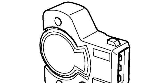
The throttle position (TP) sensor is a potentiometer attached to the throttle housing and is directly coupled to the throttle disc, the TP sensor is non adjustable. The TP sensor is used to detect closed throttle, allowing the ECM to initiate idle speed control.
The ECM supplies the TP sensor with a 5 volt feed and an earth path. The TP sensor returns a signal proportional to throttle disc position.
Throttle disc movement causes voltage across the TP sensor to vary. The control module calculates the rate of change of the voltage signal in positive (acceleration) or negative (deceleration) directions. From this, the ECM can determine the rate of movement and apply acceleration enrichment, deceleration fuel metering or over-run fuel cut-off.
Idle air control valve
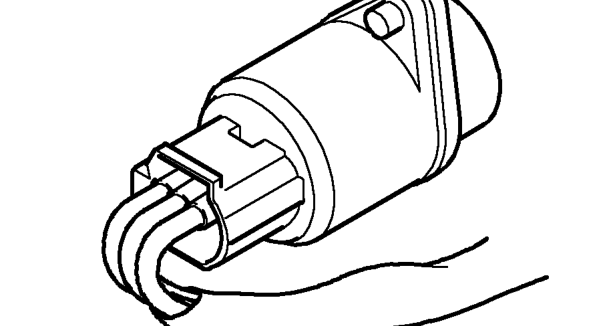
The idle air control valve is mounted on the inlet manifold and controlled by the ECM. The idle air control valve opens a pintle valve situated in an air passage in the throttle housing. Air is allowed to bypass the throttle disc and flow straight into the inlet manifold.
By changing the amount the idle air control valve is open the ECM can control engine idle speed and cold start air flow requirements by adjusting the flow of air in the passage.
During cold starting the ECM indexes the idle air control valve open slightly to provide a level of fast idle, dependent on engine coolant temperature. As the engine warms, fast idle is gradually decreased until normal operating temperature is reached.
The position of the idle air control valve should be within the range of 20 to 40 steps when the engine is idling at normal engine temperature. This ensures that the idle air control valve is able to supply varying amounts of by-pass air to compensate for all loads and temperature conditions. If the valve is identified as being outside the specified range a fault may exist. Faults should be investigated and rectified before using TestBook to adjust the idle air control valve.
Parts & tools for this job For 1995 MG MGF
- TOOLOBD2 scannerSearch: OBD2 scanner
- TOOLDigital multimeterSearch: automotive digital multimeter
- TOOLBack-probe test leadsSearch: back probe test leads
Links open Amazon search results in a new tab. As an Amazon Associate I earn from qualifying purchases.