
Throttle Position (TP) Sensor
- Make
- MG
- Model
- MGF Factory Workshop Manual
- Year
- 1995–2000
- Section
- Description and operation › Throttle Position (TP) Sensor
Throttle Position (TP) Sensor
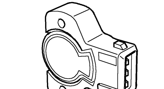
The TP sensor is mounted on the throttle body and is driven from the end of the throttle spindle. The TP sensor consists of a potentiometer which provides an analogue voltage that the ECM converts to throttle position information. The TP sensor signal is required for the following vehicle functions:
- Idle speed control
- Throttle damping
- Deceleration fuel cut off
- Engine load calculations
- Acceleration enrichment
- Full load enrichment
- Automatic gearbox shift points.
The TP sensor is a potentiometer which acts as a voltage divider in an external ECM circuit. The potentiometer consists of a 4kΩ ± 20% resistive track and a wiper arm, driven by the throttle spindle, which sweeps over the track.
The track receives a regulated 5 V ± 4% supply from the ECM, together with an earth path. As the wiper arm moves over the track it will connect to areas of different voltage ranging from 0 to 5 volts. The ’output’ from the wiper arm is connected to the ECM to provide an analogue voltage signal.
The TP sensor requires no adjustment as the ECM will learn the lower voltage limit which correspond to closed throttle.
If the TP sensor signal is missing the vehicle will continue to run but may suffer from poor idle control and throttle response. The ECM will store fault codes which can be retrieved using TestBook.
Idle Air Control (IAC) Valve
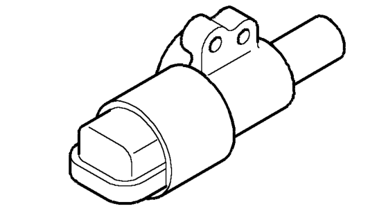
The IAC valve is located on the inlet manifold. It allows the ECM to control the engine idling speed by regulating the amount of air which by-passes the throttle valve. It also allows the ECM to provide a damping function when the throttle is closed under deceleration, this reduces hydrocarbon (HC) emissions.
The IAC valve is controlled by the ECM using a stepper motor. This consists of a core which is rotated by magnetic fields produced by two electro-magnet bobbins set at 90° to each other.
The stepper motor controls the volume of air passing through a duct which leads from the inlet manifold to a pipe connected to the throttle body. The bobbins are connected to the ECM driver circuits. Each of the four connections can be connected to 12 volts or earth, enabling four ’phases’ to be obtained. The ECM drives the four phases to obtain the desired idle speed.
When the ignition is switched off the ECM enters a power down routine which includes ’referencing’ the stepper motor. This means that the ECM will rotate the motor so that it can memorise the position when it next needs to start the engine.
Parts & tools for this job For 1995 MG MGF
- TOOLOBD2 scannerSearch: OBD2 scanner
- TOOLDigital multimeterSearch: automotive digital multimeter
- TOOLBack-probe test leadsSearch: back probe test leads
Links open Amazon search results in a new tab. As an Amazon Associate I earn from qualifying purchases.