
VVC Mechanism Control (Where Applicable)
- Make
- MG
- Model
- MGF Factory Workshop Manual
- Year
- 1995–2000
- Section
- Description and operation › VVC Mechanism Control (Where Applicable)
VVC Mechanism Control (Where Applicable)
Hydraulic Control Solenoid
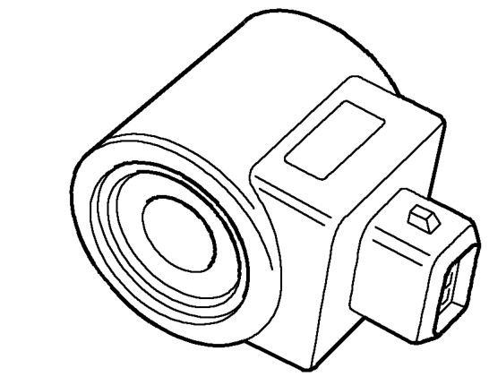
The ECM controls two solenoids in order to control the VVC mechanism. Only one solenoid will be energised at a time to either drive the VVC mechanism towards minimum cam period, or towards maximum cam period. The desired cam period is calculated by the ECM using engine speed and manifold pressure (engine load). The current cam period is measured by the ECM using the camshaft position sensor. The ECM then energises the correct solenoid in order to move the mechanism towards the desired position.
Fault Detection
If the ECM detects any faults with cam period measurement during start up and initial running, the ECM will try and drive the mechanism to minimum cam period.
If the ECM loses the cam period signal during running, the cam period will remain frozen at the last valid period. Engine speed may be limited as low as 5500 rpm depending on cam period when the fault occurred. The engine idle speed will be raised and will remain raised for the rest of the journey.
Steptronic (EM-CVT) Gearbox (Where Applicable)
The MEMS 3 ECM controls the EM-CVT unit in conjunction with the Gearbox Interface Unit (GIU) and several peripheral gearbox switches and sensors.
The GIU outputs gear selector lever position status, manual/sport selection and snow mode selection to the ECM. The ECM then provides an output to the instrument pack to display the appropriate gear position information in the LCD or illuminate the snow mode or gearbox fault warning lamps.
For further information on EM-CVT (Steptronic) gearbox See AUTOMATIC GEARBOX - ’EM-CVT’, Description and operation.
Gearbox Interface Unit (GIU)
Electronic control of the EM-CVT Steptronic gearbox operates as an integral part of the MEMS 3 system software. The ECM accepts inputs from the GIU, communicates with the GIU for gearbox control, accepts driver inputs for gear selection and communicates information to the driver via the instrument pack.
The GIU connection which supplies information to the ECM is a serial communication link. This supplies the ECM with all the driver inputs from the gearbox switches.
The ECM output to the GIU is a hardwired connection which instructs the GIU of the required ratio control motor position. This information is output in the form of 500 Hz PWM signals.
Parts & tools for this job For 1995 MG MGF
- PARTEngine gasket setSearch: MG MGF 1995 engine gasket set
- TOOLTorque wrenchSearch: 3/8 inch torque wrench
- TOOLFeeler gauge setSearch: feeler gauge set
Links open Amazon search results in a new tab. As an Amazon Associate I earn from qualifying purchases.