
Ignition Switch Signal
- Make
- MG
- Model
- MGF Factory Workshop Manual
- Year
- 1995–2000
- Section
- Description and operation › Ignition Switch Signal
Gearbox Shaft Speed Sensor
The ECM receives an input from the EM-CVT gearbox differential speed sensor which is located at the rear of the gearbox. The sensor is a Hall effect sensor which reads off the differential crown wheel teeth to provide a road speed signal. This signal is used by the ECM to determine when the vehicle is stationary and to allow accurate calculation of the true gearbox ratio.
Park/Neutral Switch
The park/neutral switch is located at the rear of the gearbox and is operated by a cam which moves via a cable with the gear shift selector lever position. An output from the park/neutral switch is connected to the ECM to enable gearbox load compensation. The ECM will adjust the IAC valve stepper motor to the appropriate position to maintain the idle speed when the gearbox is moved into and out of drive or reverse.
The park/neutral switch also operates the reverse lamps via a hardwired connection and controls a shift interlock solenoid which is fitted in selected markets only.
Ignition Switch Signal
A hardwired digital input to ECM pin 61 provides an ignition on signal. When the ECM has been idle for a period of time, it goes into ’sleep’ (power saving) mode.
When the ECM receives an ignition on signal from the ignition switch, the ECM ’wakes up’ and energises the main relay.
Main Relay
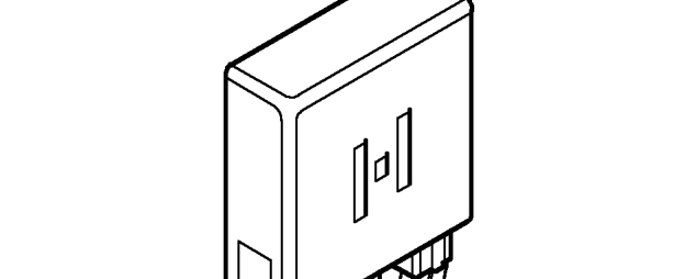
The main relay is located in the engine management relay module which is positioned behind the ECM mounting bracket. The relay module contains the main relay, the fuel pump relay and the starter relay.
The relay is normally open when the ignition is off. When the ignition is switched on to position II, the ECM provides an earth path for the relay coil which energises, closing the contacts.
A permanent battery supply is provided to the relay contacts from fuse 2 in the under bonnet fusebox. The relay supplies battery voltage to the following components:
- ECM pin 19
- H02S
- CMP sensor
- Purge valve
- Fuel injectors
- Ignition coils
- Gearbox Interface Unit (GIU) via an in-line 10A fuse.
If the main relay fails, power will not be supplied to the above components and the engine will not start. The ECM will store fault codes which can be retrieved using TestBook.
Parts & tools for this job For 1995 MG MGF
- TOOLOBD2 scannerSearch: OBD2 scanner
- TOOLDigital multimeterSearch: automotive digital multimeter
- TOOLBack-probe test leadsSearch: back probe test leads
Links open Amazon search results in a new tab. As an Amazon Associate I earn from qualifying purchases.