
Engine and gearbox (page 9 of 10)
- Make
- Rover
- Model
- 400 Workshop Manual Supplement
- Year
- 1999
- Section
- Repairs
Engine - K SeriesEngine and gearbox · page 9 of 10
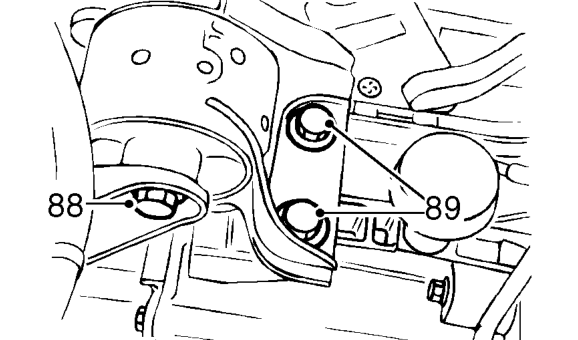
- Loosen through bolt securing gearbox mounting to body.
- Remove 2 bolts securing mounting bracket to gearbox.
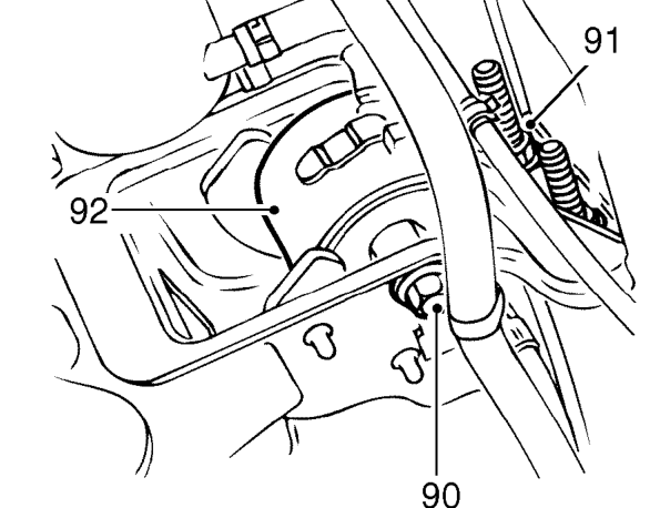
- Loosen through bolt securing engine RH mounting to body.
- Remove and discard 2 nuts securing engine RH mounting to engine.
- Remove engine RH mounting.
- Using assistance, manoeuvre and lower engine and gearbox from vehicle.
NOTE: Pay particular attention to power steering pump bracket which can catch on subframe as engine is lowered.
- Disconnect hoist from adjustable lifting bracket.
- Remove engine and gearbox from beneath vehicle.
Refit
- Using assistance, position engine and gearbox beneath vehicle.
- Connect hoist to adjustable lifting bracket 18G 1598.
- Raise and manoeuvre engine and gearbox into position in vehicle.
- Adjust lifting bracket 18G 1598 so engine is horizontal in engine compartment.
- Fit engine RH mounting to body and engine.
- Fit through bolt securing engine RH mounting to body but do not tighten.
- Fit 2 NEW nuts securing engine RH mounting to engine and tighten to 100 Nm.
- Align engine and gearbox to gearbox mounting bracket, fit 2 bolts and tighten to 80 Nm.
- Fit 2 bolts securing LH torque mounting to body and tighten to 45 Nm.
- Fit 2 bolts securing RH torque mounting to body and tighten to 45 Nm.
- Tighten through bolt securing engine RH mounting to body, to 75 Nm.
- Tighten through bolt securing gearbox mounting to body, to 75 Nm.
- Lower hoist and disconnect adjustable lifting bracket 18G 1598 from engine lifting brackets.
- Remove bolts securing engine lifting brackets 18G 1572/2 to cylinder head and remove engine lifting brackets.
- Fit engine rear mounting bracket to body and engine.
- Position engine steady bar and fit, but do not tighten, through bolt securing engine rear mounting bracket to body.
- Align engine steady bar to engine, fit bolt and tighten to 45 Nm.
- Fit bolt securing engine steady bar to manifold and tighten to 25 Nm.
- Fit 3 bolts securing engine rear mounting bracket to engine and tighten to 100 Nm.
- Tighten through bolt securing engine rear mounting to body to 80 Nm.
- Remove plugs from power steering pump and hose connections.
- Lubricate new ’O’ ring with clean power steering fluid and fit to fluid outlet hose.
Parts & tools for this job For 1999 Rover 400
- PARTEngine gasket setSearch: Rover 400 1999 engine gasket set
- TOOLTorque wrenchSearch: 3/8 inch torque wrench
- TOOLFeeler gauge setSearch: feeler gauge set
Links open Amazon search results in a new tab. As an Amazon Associate I earn from qualifying purchases.