
ABS BY4 system from VIN 144845
- Make
- Rover
- Model
- 600 Rover 600 Repair Manual - Volumes 1 and 2 - 2nd Edition
- Section
- Operation › ABS BY4 system from VIN 144845
ABS BY4 system from VIN 144845
The following description of ABS operation is for one of the front wheels. The remaining wheels operate in the same way.
Normal Braking Function
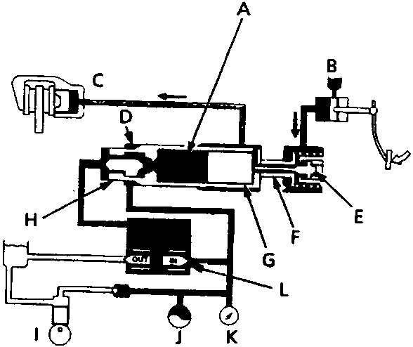
- A Back – pressure chamber
- B Master cylinder
- C Caliper
- D Chamber A
- E Cut valve – open
- F Cut valve seat
- G Piston
- H Sleeve
- I Pump
- J Accumulator
- K Pressure switch
- L Solenoid valve
In normal braking operations when ABS in not functioning, the solenoid outlet valve is closed and the inlet valve is open, transmitting the hydraulic pressure to the back – pressure chamber between the sleeve and piston, the cut valve is thus pushed by the piston. As the high – pressure is also transmitted to chamber A between the sleeve and cylinder, the sleeve also pushes the cut valve seat towards the cut valve.
Under these conditions, the cut valve is kept open, and the hydraulic pressure from the master cylinder is transmitted to the caliper for normal operation of the braking system.
When ABS is functioning
Control by reducing caliper fluid pressure
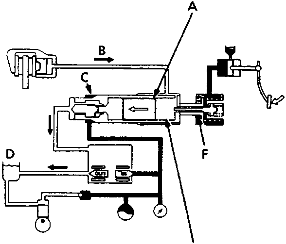
- A Piston slides
- B Pressure reduces
- C Chamber A
- D Reservoir
- E Pressure reduction chamber
- F Cut valve – close
When brake pedal pressure is excessively high, and a possibility of wheel locking occurs, the ABS control unit operates the solenoid valve, closing the inlet valve and opening the outlet valve. As a result, the high pressure in the back – pressure chamber is released to the reservoir, the piston is pushed by the caliper fluid pressure towards the back – pressure chamber. However, the cut valve seat is kept in the extended position because high pressure is transmitted to the chamber A. As the piston moves, the cut valve moves and shuts off the flow from the master cylinder, the volume of the pressure reduction chamber connected to the caliper increases, and the fluid pressure in the caliper reduces, reducing the braking force. The wheel speed is therefore restored, preventing the wheel from locking.
Parts & tools for this job For Rover 600
- TOOLOBD2 scanner with ABSSearch: OBD2 scanner ABS SRS
- TOOLDigital multimeterSearch: automotive digital multimeter
Links open Amazon search results in a new tab. As an Amazon Associate I earn from qualifying purchases.