
Wheel sensor
- Make
- Rover
- Model
- 600 Rover 600 Repair Manual - Volumes 1 and 2 - 2nd Edition
- Section
- Operation › Wheel sensor
Brakes – ABS BY4Wheel sensor
Wheel sensor
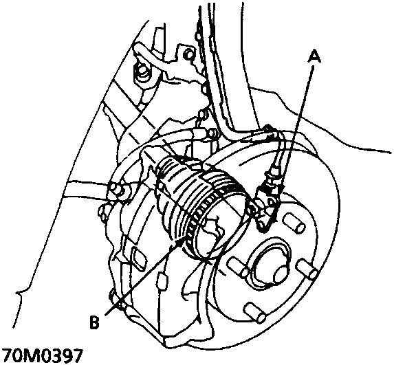
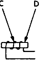
| A | Wheel sensor | D | Permanent magnet |
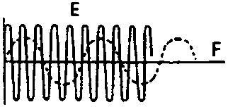
| B | Gear pulser | E | at high speed |
| C | Coil | F | at low speed |
The contactless type wheel sensor is comprised of a permanent magnet and coil which detects the rotational speed of the gear pulser on each wheel hub (front wheel: outboard joint of the driveshaft, rear wheel: hub bearing unit). The magnetic flux around the coil in the wheel sensor alternates, generating voltages with frequency in proportion to wheel rotational speed. These pulses are feed into the ABS control unit and the control unit identifies the idividual wheel speeds.
Parts & tools for this job For Rover 600
- TOOLOBD2 scannerSearch: OBD2 scanner
- TOOLDigital multimeterSearch: automotive digital multimeter
- TOOLBack-probe test leadsSearch: back probe test leads
Links open Amazon search results in a new tab. As an Amazon Associate I earn from qualifying purchases.