
Pressure Switch
- Make
- Rover
- Model
- 600 Rover 600 Repair Manual - Volumes 1 and 2 - 2nd Edition
- Section
- Operation › Pressure Switch
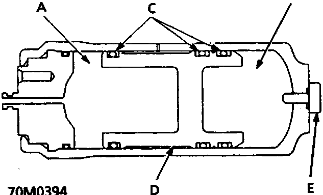
70M0394
- A Fluid chamber
- B Gas chamber – nitrogen gas filled
- C 'O' rings
- D Free piston
- E Relief plug
The high – pressure brake fluid discharged from the pump is fed to the solenoids and pistons, but the passage to the solenoids and pistons is normally closed. Consequently, the high pressure brake fluid is accumulated in the accumulator.
The accumulator consists of two chambers separated by a free piston; that is, a fluid chamber where the brake fluid is accumulated and a chamber filled with high pressure nitrogen gas to maintain the fluid at a given pressure.
When the ABS operates, the constant high – pressure brake fluid in the accumulator is supplied to the pistons.
Pressure Switch
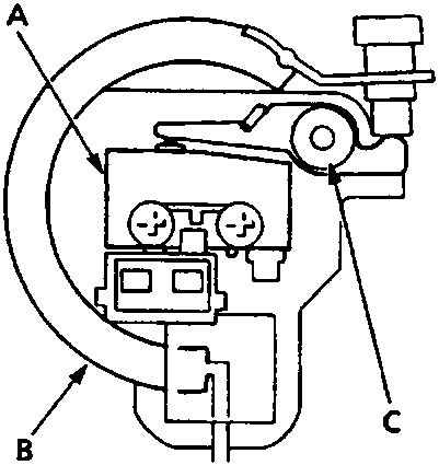
70M0395
- A Micro – switch
- B Bourdon tube
- C Sensing lever
The pressure switch monitors the pressure accumulation (pressure from the pump) in the accumulator. When the pressure in the accumulator rises, the Bourdon tube in the pressure switch deforms outward, which in turn activates the micro – switch by the force of the spring attached to the sensing lever. When the pressure in the accumulator drops due to ABS operation, the Bourdon tube moves in the opposite direction and the micro – switch is eventually turned off.
The ABS control unit detects the fluid pressure in the accumulator by the ON/OFF signals from the pressure switch.
Parts & tools for this job For Rover 600
- TOOLOBD2 scannerSearch: OBD2 scanner
- TOOLDigital multimeterSearch: automotive digital multimeter
- TOOLBack-probe test leadsSearch: back probe test leads
Links open Amazon search results in a new tab. As an Amazon Associate I earn from qualifying purchases.