
ABS BY4 system from VIN 144845 (page 2 of 2)
- Make
- Rover
- Model
- 600 Rover 600 Repair Manual - Volumes 1 and 2 - 2nd Edition
- Section
- Operation
Brakes – ABS BY4ABS BY4 system from VIN 144845 · page 2 of 2
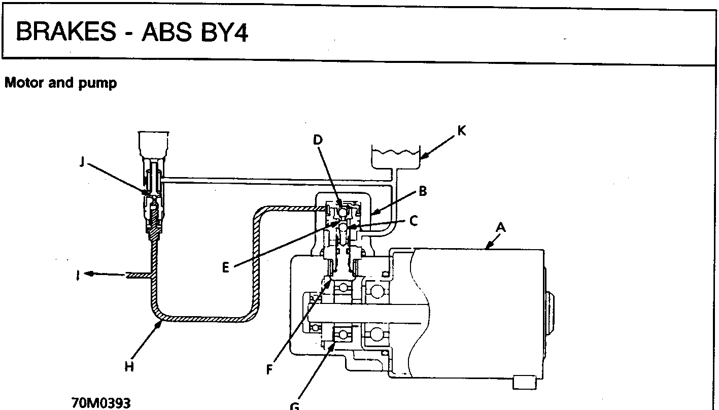
70M0393
| A | Motor | G | Eccentric bearing |
| B | Pump | H | High pressure circuit |
| C | Check valve – inlet | I | To accumulator, solenoids and pistons |
| D | Check valve – outlet | J | Relief valve |
| E | Plunger chamber | K | Reservoir |
| F | Plunger |
As the motor rotates, it drives the pluger – type ABS pump and raises the brake fluid pressure to approximately 25,000 kPa, 250 bar, 3,600 lb/in². The eccentric bearing is attached to the motor shaft end; it contains the pump plunger.
When the plunger is pushed, the brake fluid in the plunger chamber is pressurised and fed to the accumulator, solenoid and pistons, via the check valve. When the pressure in the accumulator exceeds 35,000 kPa, 350 bar, 5,000 lb/in², the relief valve opens to release the excess pressure to the reservoir.
Parts & tools for this job For Rover 600
- TOOLOBD2 scanner with ABSSearch: OBD2 scanner ABS SRS
- TOOLDigital multimeterSearch: automotive digital multimeter
Links open Amazon search results in a new tab. As an Amazon Associate I earn from qualifying purchases.