
Abs control unit
- Make
- Rover
- Model
- 600 Rover 600 Repair Manual - Volumes 1 and 2 - 2nd Edition
- Section
- Operation › Abs control unit
ABS CONTROL UNIT
The ABS control unit consists of a main function section, which controls the operation of the anti - lock brake system, and sub - function, which controls the pump motor and Self - diagnosis.
For safety, the main function consists of 2 systems, thus the ABS control unit will only activate a solenoid valve when the outputs of the 2 systems agree.
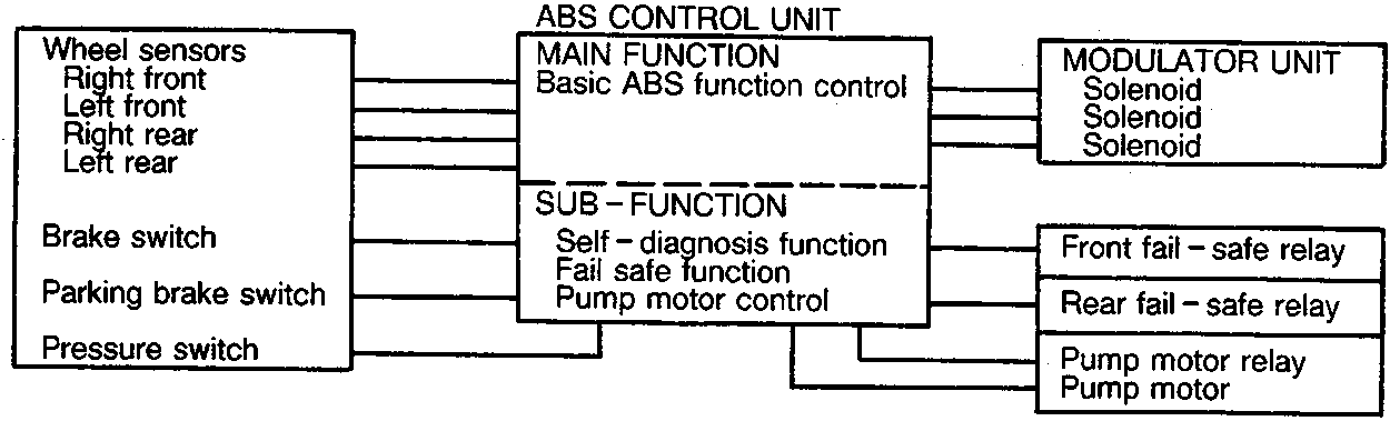
Main Function
The main function section of the ABS control unit performs calculations on the basis of the signals from each wheel sensor and controls the operation of the anti - lock brake system by operating the solenoid valves in the modulator unit for each front brake and Select Low control for the two rear brakes. Select Low control of the rear wheels means that the rear wheel that would lock first determines the ABS activation for both rear wheels.
Sub - function
The sub - function section gives driving signals to the pump motor and also gives Self - diagnosis signals necessary for backing up the anti - lock brake system.
Pump motor control
The control unit monitors the brake fluid pressure in the accumulator by the pressure switch ON/OFF signals. The ABS control unit turns the pump on when the pressure in the accumulator drops, and stops the pump when the pressure rises to the specified value.
If the pressure does not reach the specified value after the motor has operated continuously for a specified period, the ABS control unit stops the motor and activates the ABS indicator light.
Self - Diagnostic Function
The self - diagnosis function, provided by the sub - function of the ABS control unit, monitors the main system functions by constantly transmitting the data between the 2 Central Processing Units (CPU's). When an abnormality is detected, the ABS control unit turns the ABS indicator light on and ABS is inhibited. The diagnostic trouble code (DTC) is recorded in the control unit, which can be read from the frequency of blinks given by the ABS indicator light. The basic braking system continues to operate normally.
There is also a check mode of the self diagnosis system, when the ignition is switched on. The ABS indicator light comes on and stays on for a few seconds after the engine has started to signify that the self diagnosis system is functional.
Parts & tools for this job For Rover 600
- TOOLOBD2 scanner with ABSSearch: OBD2 scanner ABS SRS
- TOOLDigital multimeterSearch: automotive digital multimeter
Links open Amazon search results in a new tab. As an Amazon Associate I earn from qualifying purchases.