
Kickback and Pump Operation
- Make
- Rover
- Model
- 600 Rover 600 Repair Manual - Volumes 1 and 2 - 2nd Edition
- Section
- Operation › Kickback and Pump Operation
Brakes – ABS BY4Kickback and Pump Operation · page 1 of 2
Kickback and Pump Operation
- When the engine is started, the ABS control unit begins the initial diagnosis and operates the solenoid valve one time. The kickback may be felt when the brake pedal is depressed.
- When the ABS control unit detects the pressure switch Off signal during the initial diagnosis, it operates the pump, and performs the pump motor over – run diagnosis. Therefore, there are 2 cases where the pump motor operates or does not operate after the engine is started.
- Normally, after the initial diagnosis, the pump operates based on the pressure switch signal, regardless of the vehicle speed.
Fault Finding
- When 2 or 3 DTC’s are stored in the control unit, perform fault finding for the DTC that appears first.
- When a customer’s reported problem cannot be verified on the car, ask the customer about the conditions when the ABS indicator light came ON, and test drive the car under those conditions, if possible. When the ABS indicator light does not come ON during the test, check for loose terminals and check by shaking the harness and connectors.
- The connector terminal numbers are viewed from the WIRE SIDE of the female terminals, and from the TERMINAL SIDE for the male terminals
Note: The ABS indicator light will come on and the ABS control unit will memorize a DTC when there is insufficient battery voltage to the ABS control unit. An example would be when the battery is so weak that the car must be jump – started. After the battery is recharged, the ABS indicator light will work normally after the engine is stopped and restarted.
However, after recharging the battery, the DTC must be cleared from the ABS control unit memory by disconnecting the ABS B2 (15 amp) fuse in the under bonnet fuse box for at least three seconds.
Diagnostic Trouble Code (DTC):
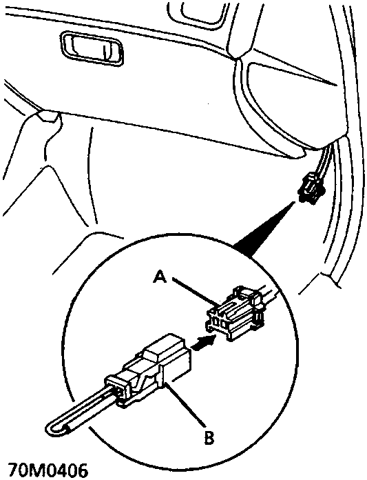
- A Service check connector (2P)
- B SCS Short connector 18G 1724
- Locate service check connector (2P) above the side panel (passenger’s side) and connect SCS short connector 18G 1724.
- Turn the ignition switch on, but do not start the engine.
- Record the frequency of flashes from the ABS indicator light.
The frequency of flashes indicates the diagnostic trouble code (DTC).
Parts & tools for this job For Rover 600
- TOOLOBD2 scanner with ABSSearch: OBD2 scanner ABS SRS
- TOOLDigital multimeterSearch: automotive digital multimeter
Links open Amazon search results in a new tab. As an Amazon Associate I earn from qualifying purchases.