
Kickback and Pump Operation (page 2 of 2)
- Make
- Rover
- Model
- 600 Rover 600 Repair Manual - Volumes 1 and 2 - 2nd Edition
- Section
- Operation
Brakes – ABS BY4Kickback and Pump Operation · page 2 of 2
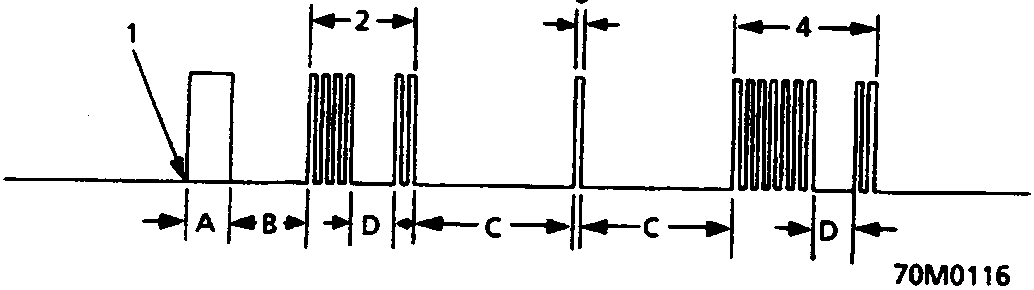
- Ignition ON
- Fault code 4 – 2
- Fault code 1
- Fault code 7 – 2
| A | ABS indicator light on for 1 second |
| B | 2 second pause |
| C | 5 second pause |
| D | 1 second pause |
Note:
- The ABS control unit can indicate three DTCs (one, two or three problems).
- If the ABS indicator light does not illuminate, use Microcheck to find the problem.
- If you miscount the frequency of flashes, turn the ignition switch OFF then ON to cycle the ABS indicator light again.
- After the repair is completed, disconnect the ABS B2 (15 A) fuse in the under-bonnet ABS fuse/relay box for at least three seconds to erase the ABS control unit's memory. Then turn the ignition key on again and recheck.
- The memory is erased if the connector is disconnected from the ABS control unit or the ABS control unit is removed from the body.
- After recording the DTC (if applicable), refer to the Diagnostic Trouble Code Chart.
Parts & tools for this job For Rover 600
- TOOLOBD2 scanner with ABSSearch: OBD2 scanner ABS SRS
- TOOLDigital multimeterSearch: automotive digital multimeter
Links open Amazon search results in a new tab. As an Amazon Associate I earn from qualifying purchases.