
Installation
- Make
- Rover
- Model
- 600 Rover 600 Repair Manual - Volumes 1 and 2 - 2nd Edition
- Section
- Repairs › Installation
ClutchInstallation
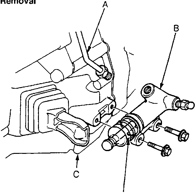
- Clutch pipe
- Slave cylinder
- Clutch housing
- Boot
- Disconnect the clutch pipe from the slave cylinder.
CAUTION: Do not allow brake fluid to contact paint finished surfaces as paint may be damaged. If spilled, remove fluid and clean area with clean warm water.
CAUTION: Plug the connections.
- Remove the slave cylinder from the clutch housing.
Installation
- Connect the clutch pipe.
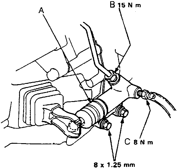
- Slave cylinder
- Clutch pipe
- Bleeder screw
Note: Use only Urea Grease UM264.
- Install the slave cylinder on the clutch housing.
- Bleed the clutch hydraulic system:
- Attach a hose to the bleeder screw and suspend the hose in a container of brake fluid.
- Make sure there is an adequate supply of fluid at the clutch master cylinder, then slowly pump the clutch pedal until no more bubbles appear at the bleeder hose.
- Refill the clutch master cylinder fluid when done.
- Use only DOT 3 or 4 brake fluid.
Parts & tools for this job For Rover 600
- PARTClutch kitSearch: Rover 600 clutch kit
- TOOLClutch alignment toolSearch: clutch alignment tool
- FLUIDGear oilSearch: Rover 600 manual gearbox oil
Links open Amazon search results in a new tab. As an Amazon Associate I earn from qualifying purchases.