
Removal
- Make
- Rover
- Model
- 600 Rover 600 Repair Manual - Volumes 1 and 2 - 2nd Edition
- Section
- Repairs › Removal
ClutchRemoval
Removal
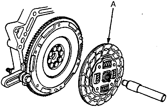
33M0063
- A Clutch disc
Remove the clutch disc and special tools.
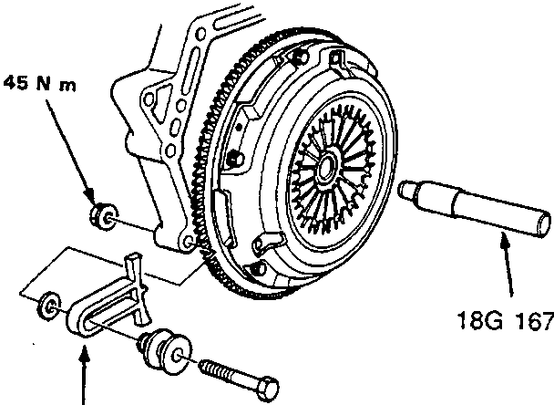
33M0061
Install the special tools as shown.
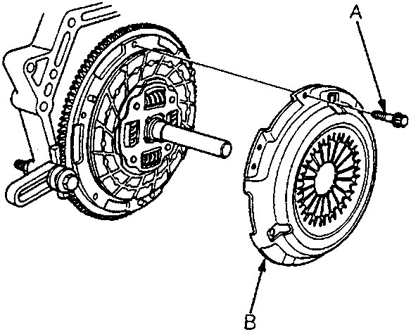
33M0062
- A Mounting bolt
- B Pressure plate
To prevent warping, unscrew the pressure plate mounting bolts in a crisscross pattern in several steps, then remove the pressure plate.
Parts & tools for this job For Rover 600
- PARTClutch kitSearch: Rover 600 clutch kit
- TOOLClutch alignment toolSearch: clutch alignment tool
- FLUIDGear oilSearch: Rover 600 manual gearbox oil
Links open Amazon search results in a new tab. As an Amazon Associate I earn from qualifying purchases.