
Master Cylinder Removal/Installation
- Make
- Rover
- Model
- 600 Rover 600 Repair Manual - Volumes 1 and 2 - 2nd Edition
- Section
- Repairs › Master Cylinder Removal/Installation
ClutchMaster Cylinder Removal/Installation
Master Cylinder Removal/Installation
CAUTION: Do not allow brake fluid to contact paint finished surfaces as paint may be damaged. If spilled, remove fluid and clean area with clean warm water.
CAUTION: Plug the connections.
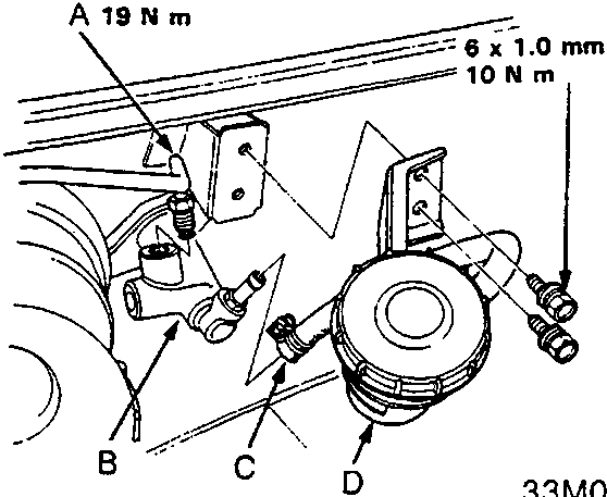
- Clutch Pipe
- Clutch Master Cylinder
- Reservoir Hose
- Reservoir
- Remove the reservoir hose from the clutch master cylinder and drain the brake fluid into a suitable container.
- Remove the reservoir from the engine compartment bulkhead.
- Disconnect the clutch pipe from the clutch master cylinder.
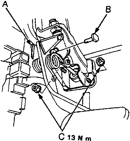
- Cotter Pin
- Pedal Pin
- Nuts
- Pry out the cotter pin and pull the pedal pin out of the yoke. Remove the nuts.
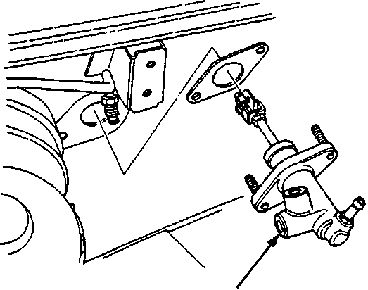
- Clutch Master Cylinder
- Remove the clutch master cylinder.
- Install the clutch master cylinder in the reverse order of removal.
- Bleed the clutch hydraulic system, see Slave Cylinder – Installation.
Parts & tools for this job For Rover 600
- TOOLBrake bleeder kitSearch: one man brake bleeder kit
- FLUIDBrake fluidSearch: brake fluid
- TOOLBrake line flaring toolSearch: brake line flaring tool
Links open Amazon search results in a new tab. As an Amazon Associate I earn from qualifying purchases.